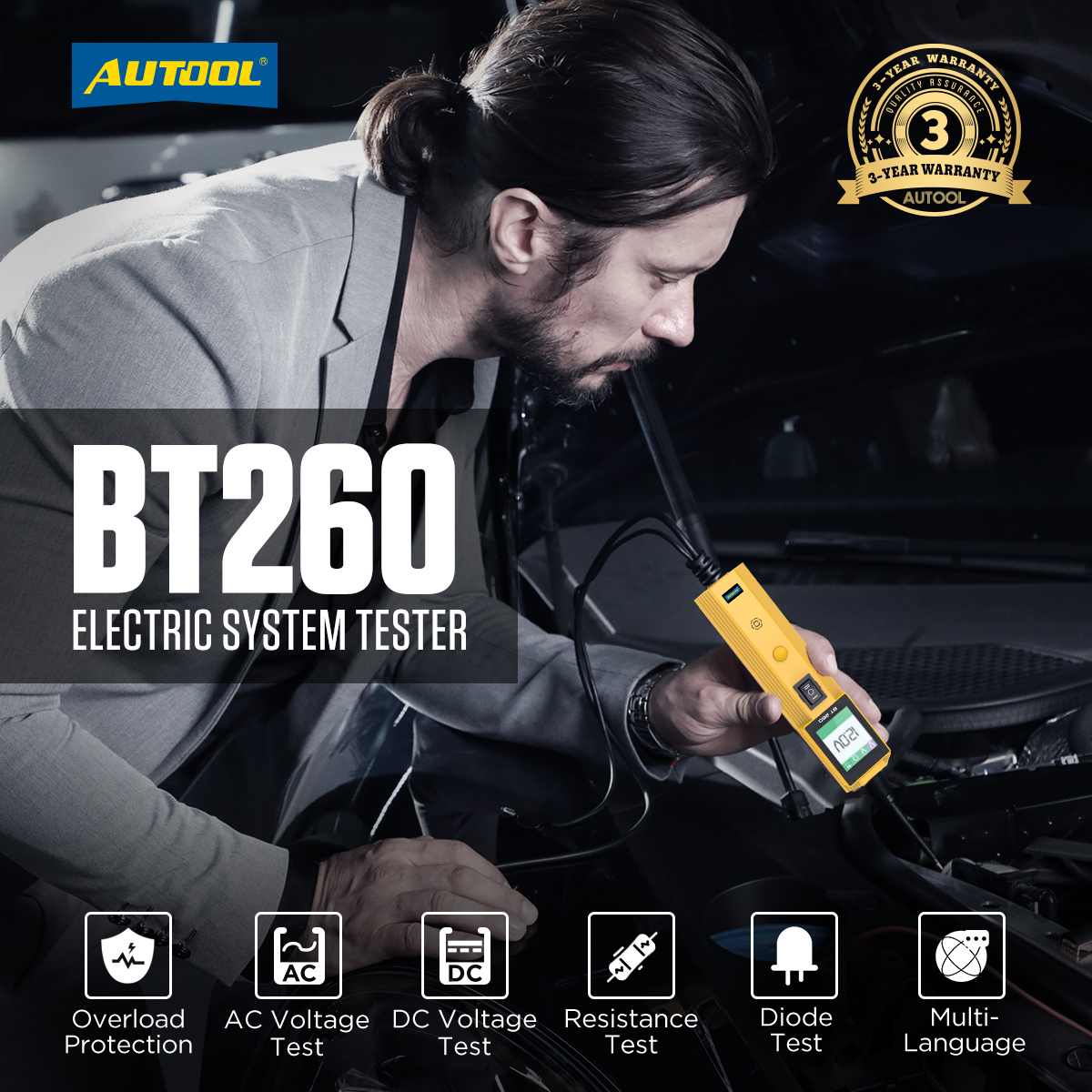
BT260 Electrical Circuit Tester For Trucks
The AUTOOL BT260 Electrical System Tester uses electromagnetic induction to detect voltage signals. When the device's metal probe comes into contact with a circuit, its built-in high-sensitivity sensing element can detect the alternating magnetic field around the circuit. If current is flowing through the circuit, the LED indicator on the device will light up instantly, providing you with a clear and accurate indication of the electrode polarity.


Working Principle
The AUTOOL BT260 Electrical System Tester uses electromagnetic induction to detect voltage signals. When the device’s metal probe comes into contact with a circuit, its built-in high-sensitivity sensing element can detect the alternating magnetic field around the circuit. If current is flowing through the circuit, the LED indicator on the device will light up instantly, providing you with a clear and accurate indication of the electrode polarity.
Features
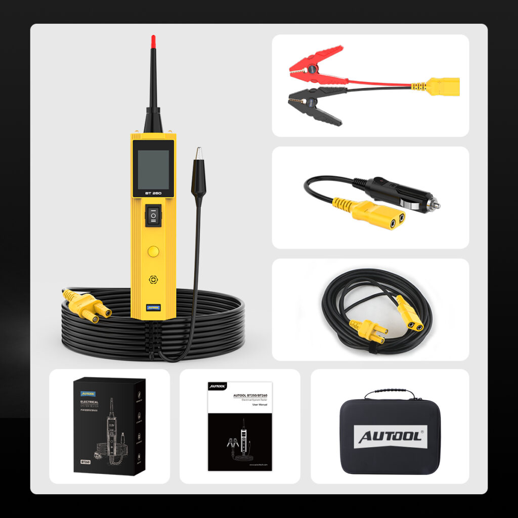
Professional Circuit Tester: Powered directly through the car battery or cigarette lighter socket, it requires no additional batteries or cables. In addition to testing circuit issues related to vehicle components, it can also be used as a temporary power source to supply power for testing parts such as radiator fans, starter motors, relays, power window regulators, and windshield wipers.
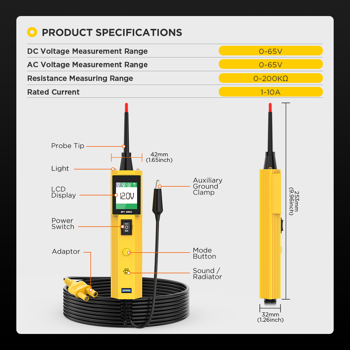
Wide Vehicle Compatibility: With a voltage testing range of 0–65V, it supports testing on various types of vehicles including cars, motorcycles, vans, trucks, excavators, boats, and RVs.
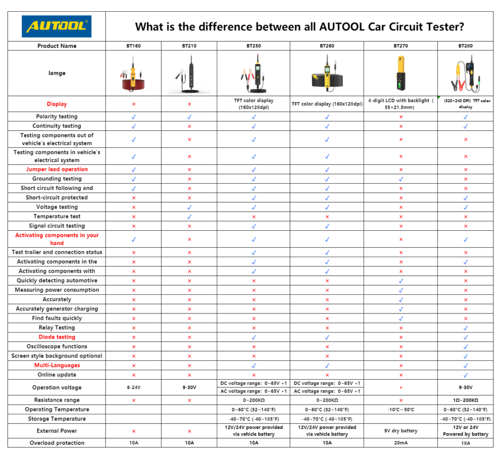
Multiple application functions: The circuit tester is equipped with four testing modes, which can be flexibly switched between DC voltage test, AC voltage test, resistance test and diode test, and supports polarity identification, continuity test, signal circuit test, bad ground test, line tracking and positioning, jumper detection, activation of components and so on.
Multiple Functions: The circuit tester features four detection modes—DC voltage test, AC voltage test, resistance test, and diode test—which can be switched flexibly. It supports polarity identification, continuity testing, signal circuit testing, poor grounding testing, wire tracing and positioning, jumper detection, component activation, and more.
Easily Locate Faults: With the BT260, you can easily identify issues such as open circuits, continuity, and short circuits. It is ideal for checking vehicle switches, relays, headlights, taillights, faulty sockets, diodes, fuses, wiring, and overall circuit connectivity.
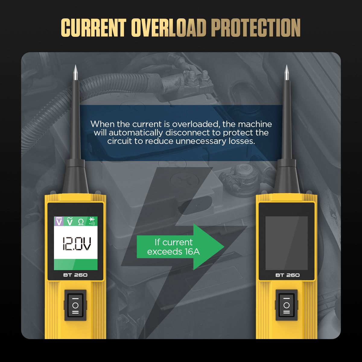
Automatic Short-Circuit Protection: The circuit tester is equipped with short-circuit protection. In the event of an overload or short circuit, the device will automatically restart, ensuring the safety of both the tester and the vehicle.
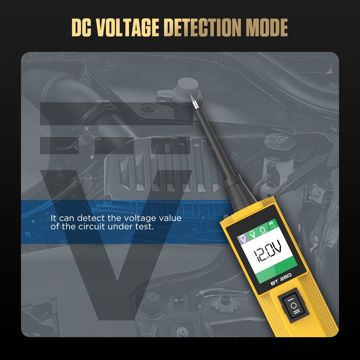
DC Voltage Testing: Offers a resolution of up to 0.1V and an accuracy of ±0.2V, enabling precise measurement of voltage at various points within the vehicle’s electrical system.
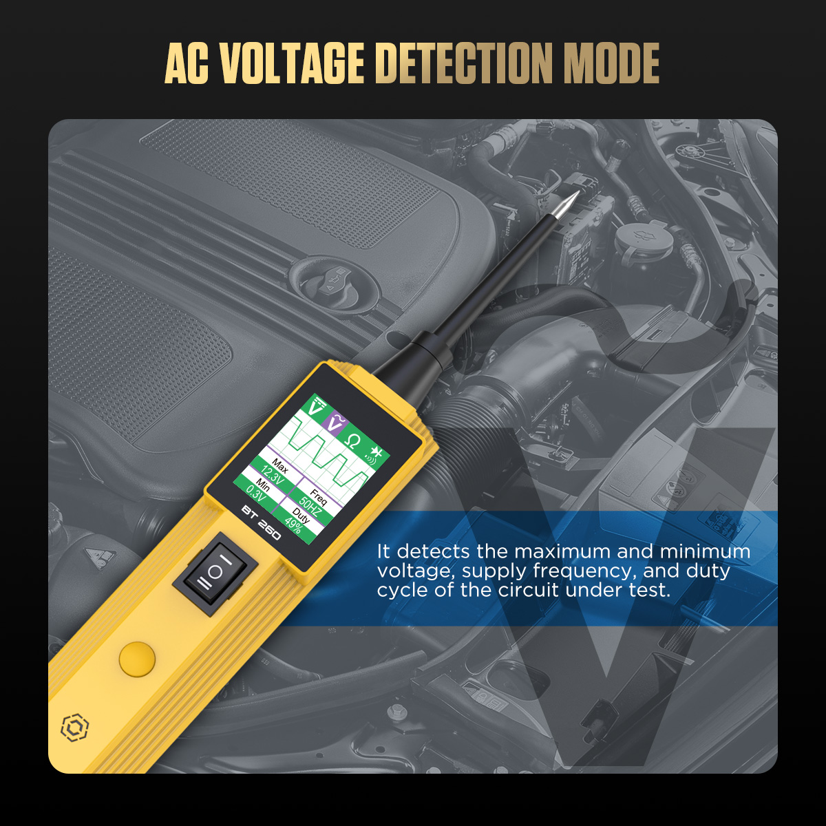
AC Voltage Testing: Capable of detecting the maximum and minimum voltage values of the tested circuit, as well as power frequency and duty cycle.
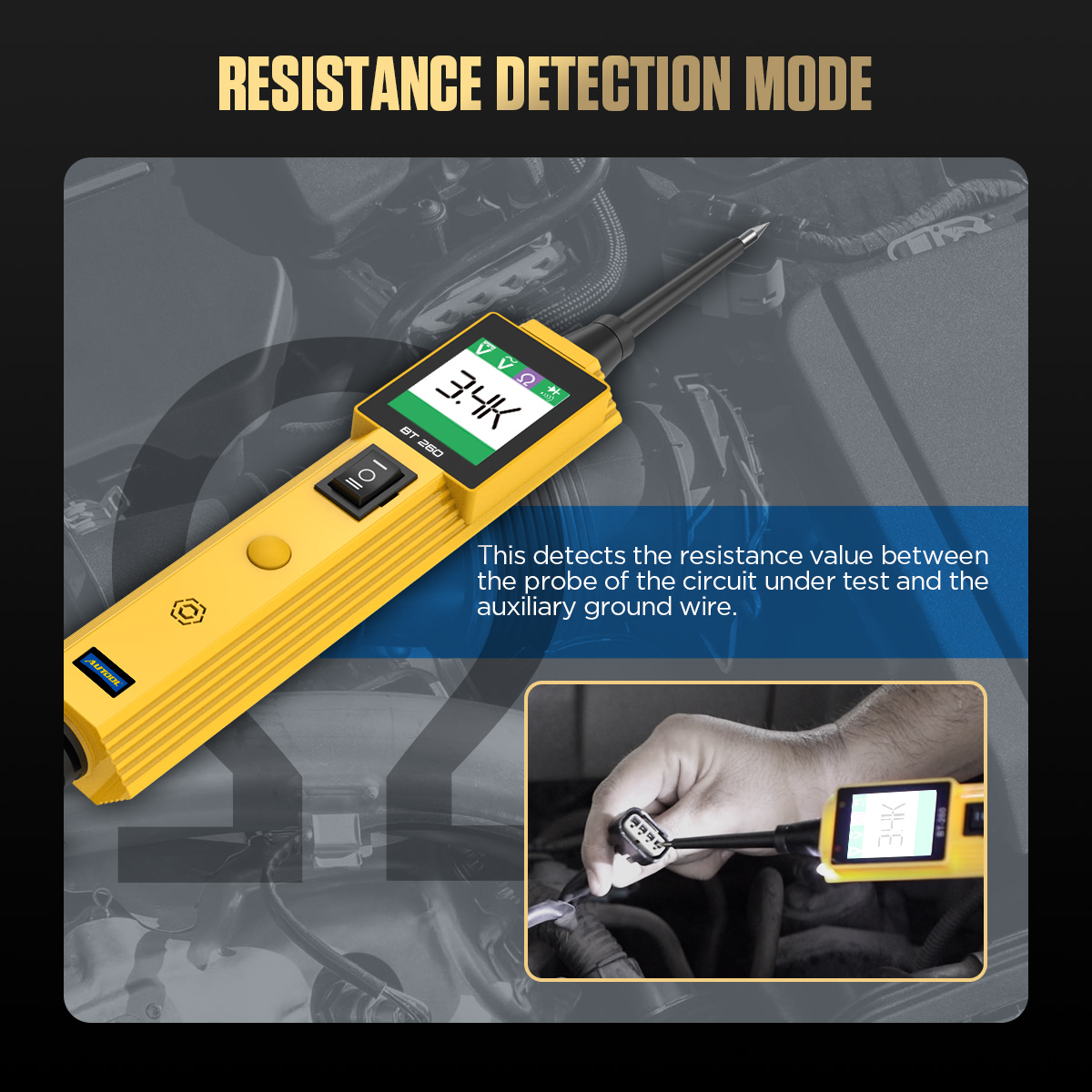
Resistance Testing: Supports a resistance range of 0–200kΩ, allowing you to measure the resistance value between the test probe and the auxiliary ground wire in the circuit.
Diode Testing: Quickly checks the operating status of diode components and accurately detects open circuits and continuity in the wiring.
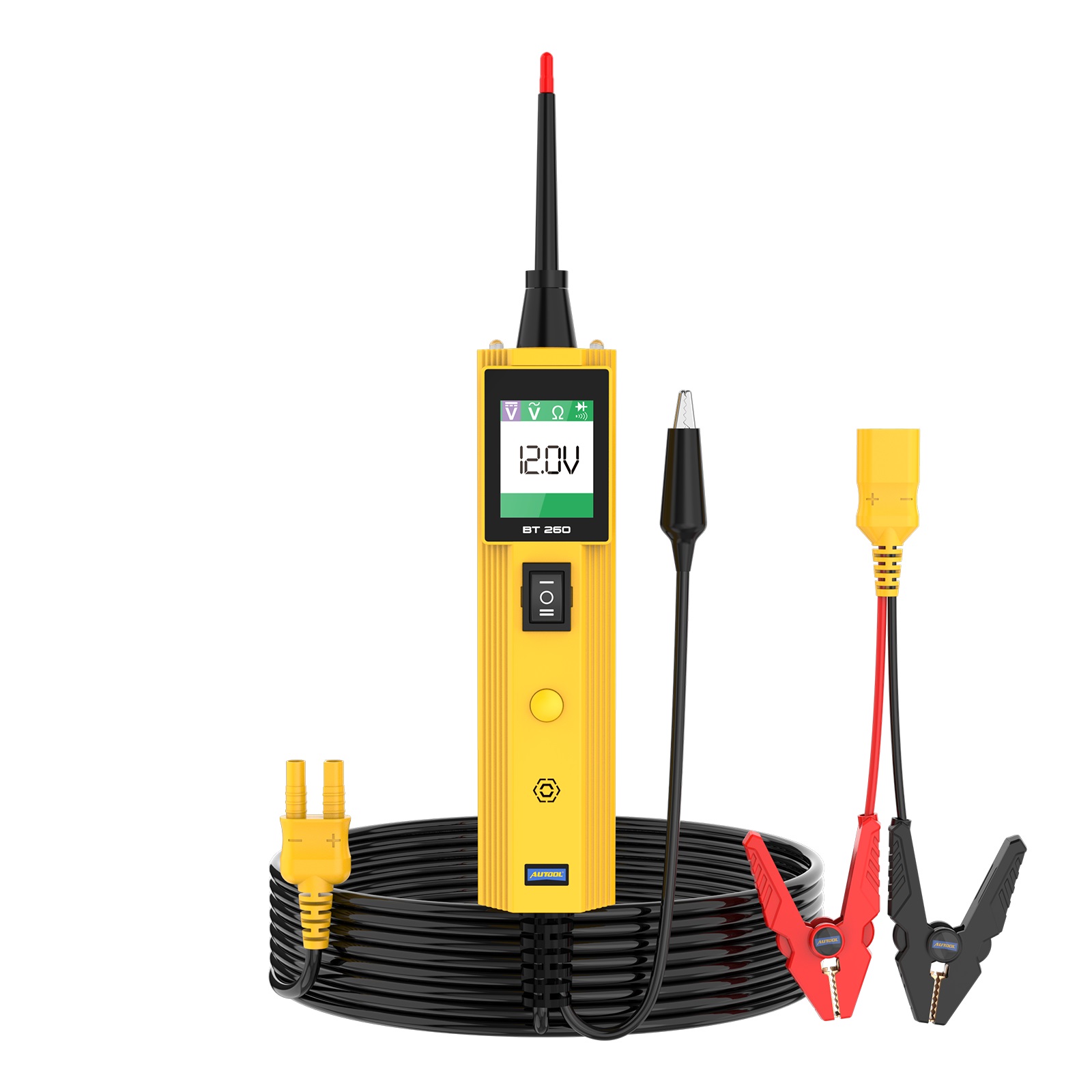
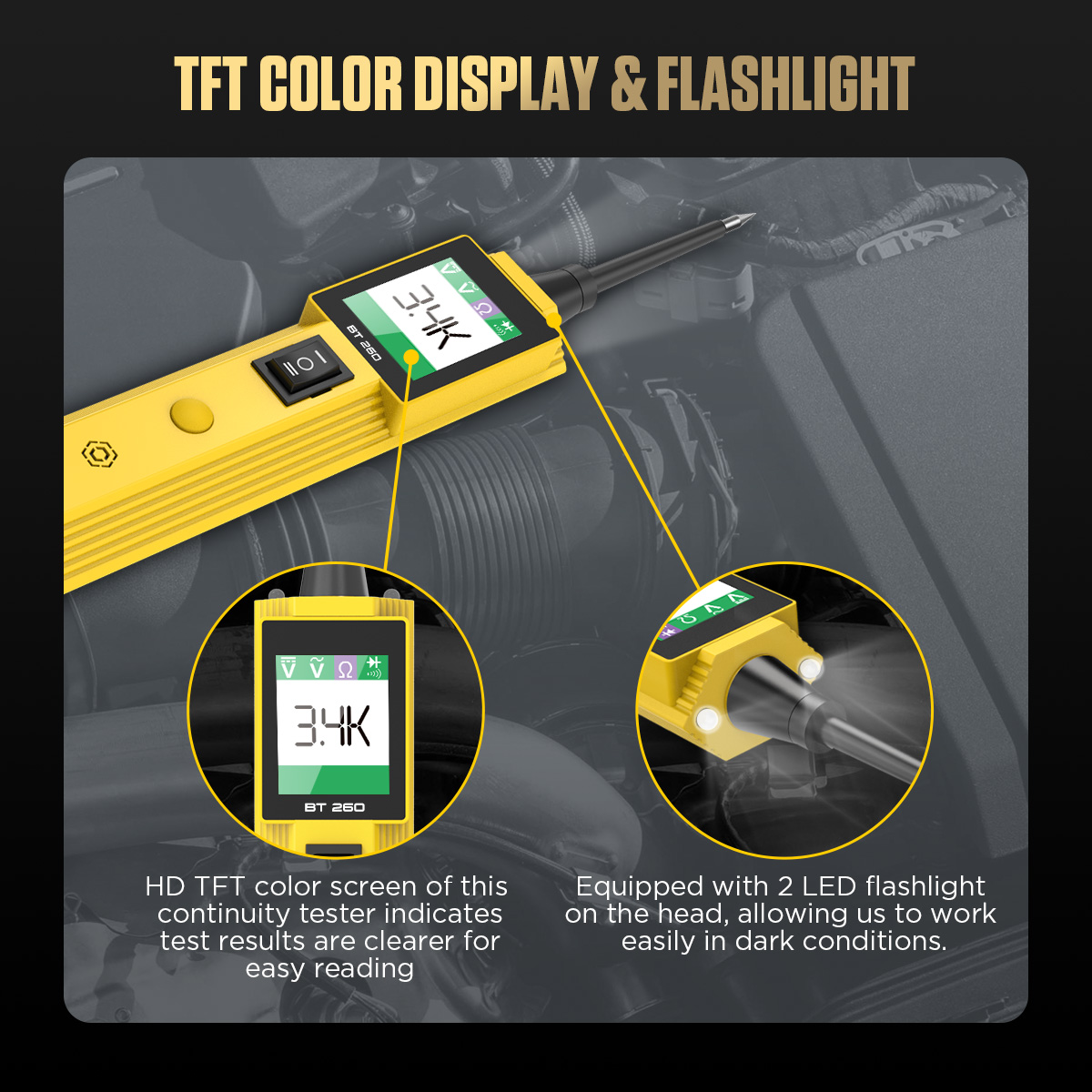
Backlit HD Color Display: Equipped with a 1.7-inch color screen, it provides clear visibility of test data even in bright or dim environments.
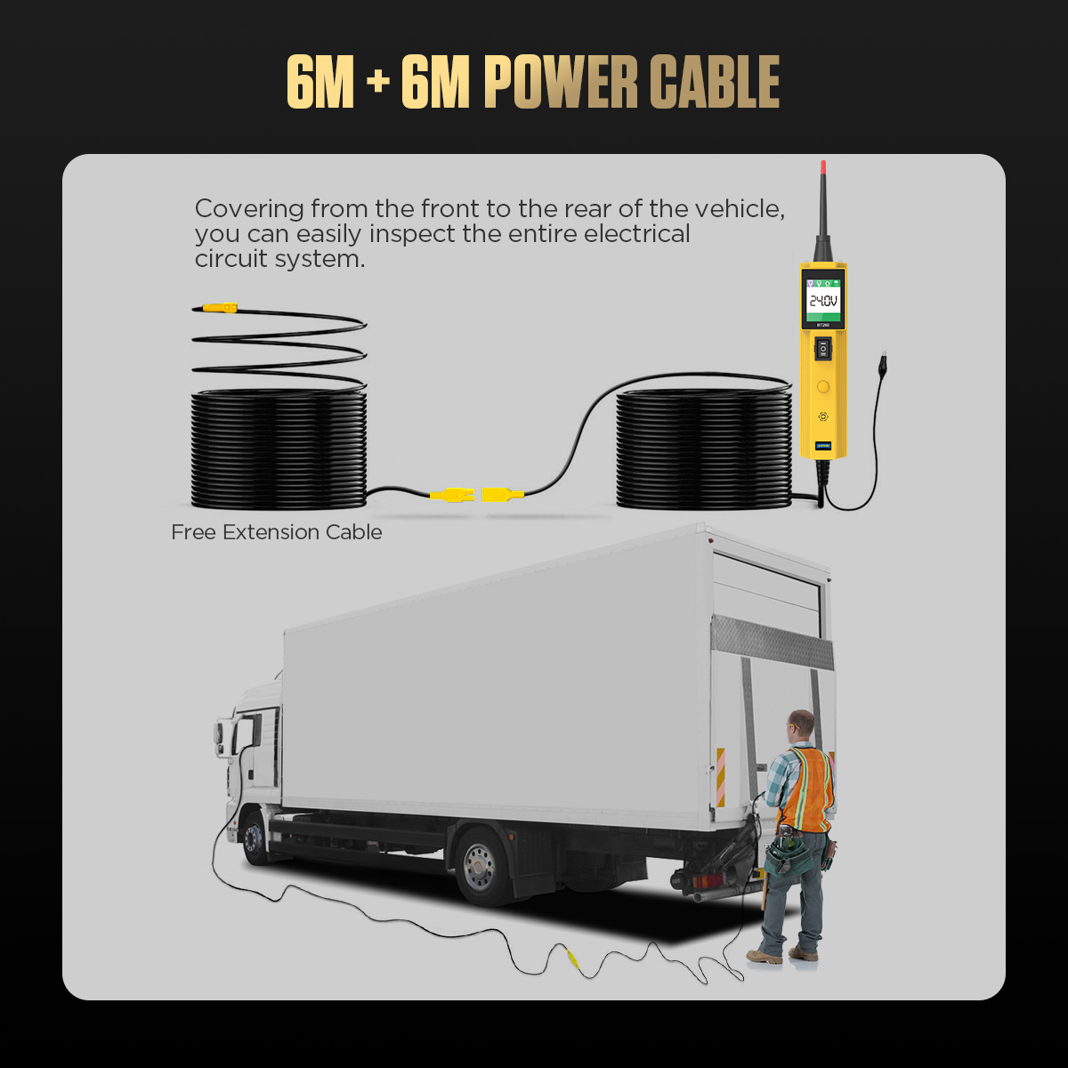
12-Meter Test Lead: Offers convenient testing, covering the entire vehicle from front to rear, making it easy to inspect the full electrical system.
Multiple Language Options: Supports Chinese, English, Russian, German, Portuguese, French, Italian, Spanish, and Polish.
Operating Instructions
Note: When the device is powered on for the first time, the buzzer will emit a “beep” sound and the LED work light will turn on automatically. You can choose to turn the light on or off based on your needs. Before performing your first circuit or component test, please run a self-check to ensure the circuit tester is in proper working condition.
Self-Check Steps
1. Connect the red clamp to the positive terminal of the car battery and the black clamp to the negative terminal.
2. Press the power switch “-” button forward to activate the probe with positive voltage. The LED indicator and screen will light up in red, and the screen will display 0.0V.
3. Press the power switch “=” button backward to activate the probe with negative voltage. The LED indicator and screen will light up in green, and the screen will display 0.0V.
4. If the above tests display correctly, it indicates that the device is in good condition and ready for use.
Polarity Test
1. Connect the red clamp to the positive terminal of the car battery and the black clamp to the negative terminal.
2. Press the mode button briefly to select the DC voltage mode.
3. Touch the tip of the circuit tester probe to a test point with an unknown polarity.
4. If the LED and screen on the circuit tester light up red, and the screen displays a voltage value, it indicates the test point is positive voltage.
5. If the LED and screen on the circuit tester light up green, and the screen displays a voltage value, it indicates the test point is negative voltage.
Continuity Test
Connect the red clamp to the positive terminal of the car battery and the black clamp to the negative terminal.
Press the mode button briefly to select the resistance mode.
Touch the probe to the vehicle chassis or an auxiliary ground wire.
If the tester’s LED and screen light up green and the display shows 0.0Ω, it indicates the vehicle’s circuit system is continuous.
If the LED and screen do not light up green, it indicates the circuit system is open or disconnected.
Signal Circuit Test
Connect the red clamp to the positive terminal of the car battery and the black clamp to the negative terminal.
Press the mode button briefly to select the AC voltage test mode.
Touch the probe to the vehicle chassis or an auxiliary ground wire, and connect a vacuum pump to the M.A.P. sensor.
Touch the probe of the circuit tester to the positive terminal of the M.A.P. sensor and observe the waveform on the display (a normal signal should appear as a sine wave).
Activate the vacuum pump.
Release the vacuum pump and observe the readings on the display.
If the waveform displayed on the screen is abnormal, it indicates a malfunction in the sensor.
Ground Fault Test
Connect the red clamp to the positive terminal of the car battery and the black clamp to the negative terminal.
Briefly press the mode button to select the diode test mode.
Press the “-” button on the tester; the LED and screen will turn red, and the metal probe will output positive voltage.
Touch the probe to the negative terminal (ground point) of the component, as close to the component as possible.
If the grounding is good, the tester’s LED and screen will turn green.
If the grounding is poor or the contact point is not a ground, the LED and screen will remain red.
Wire Tracing Test
Connect the red clamp to the positive terminal of the car battery and the black clamp to the negative terminal.
Briefly press the mode button to select the diode test mode.
Press the “-” button on the tester; the LED and screen will light up red, and the metal probe will output positive voltage.
Remove the faulty fuse from the fuse box and begin tracing from the load side of the fuse socket, tapping the circuit contact points quickly with the probe.
If the LED and screen turn green, it indicates a short circuit or an overloaded component in the current section of the circuit.
Follow the color or code markings on the traced wire to locate the next node along the wiring harness or cable path.
Disconnect the connection at the node, then use the same quick tapping method to test both the contact point before and after the node.
Confirm the direction in which the problem occurs and continue tracing. If a component is encountered, test it separately until the end of the circuit is reached, identifying and eliminating the short circuit location or overloaded component.
| BT260 | |
| DC Voltage Measurement Range | 0-65V |
| AC Voltage Measurement Range | 0~65V |
| Resistance Measuring Range | 0-200KΩ |
| Rated Current | 1-10A |