Working Principle
The AUTOOL BT210 Bidirectional Voltage Tester utilizes electromagnetic to detect voltage signals. When the device’s metal probe approaches an energized circuit, its built-in high-sensitivity sensing element detects the alternating magnetic field around the circuit. If current flows through the circuit, the LED indicator on the device lights up instantly, providing a clear and accurate identification of electrode properties.
Features
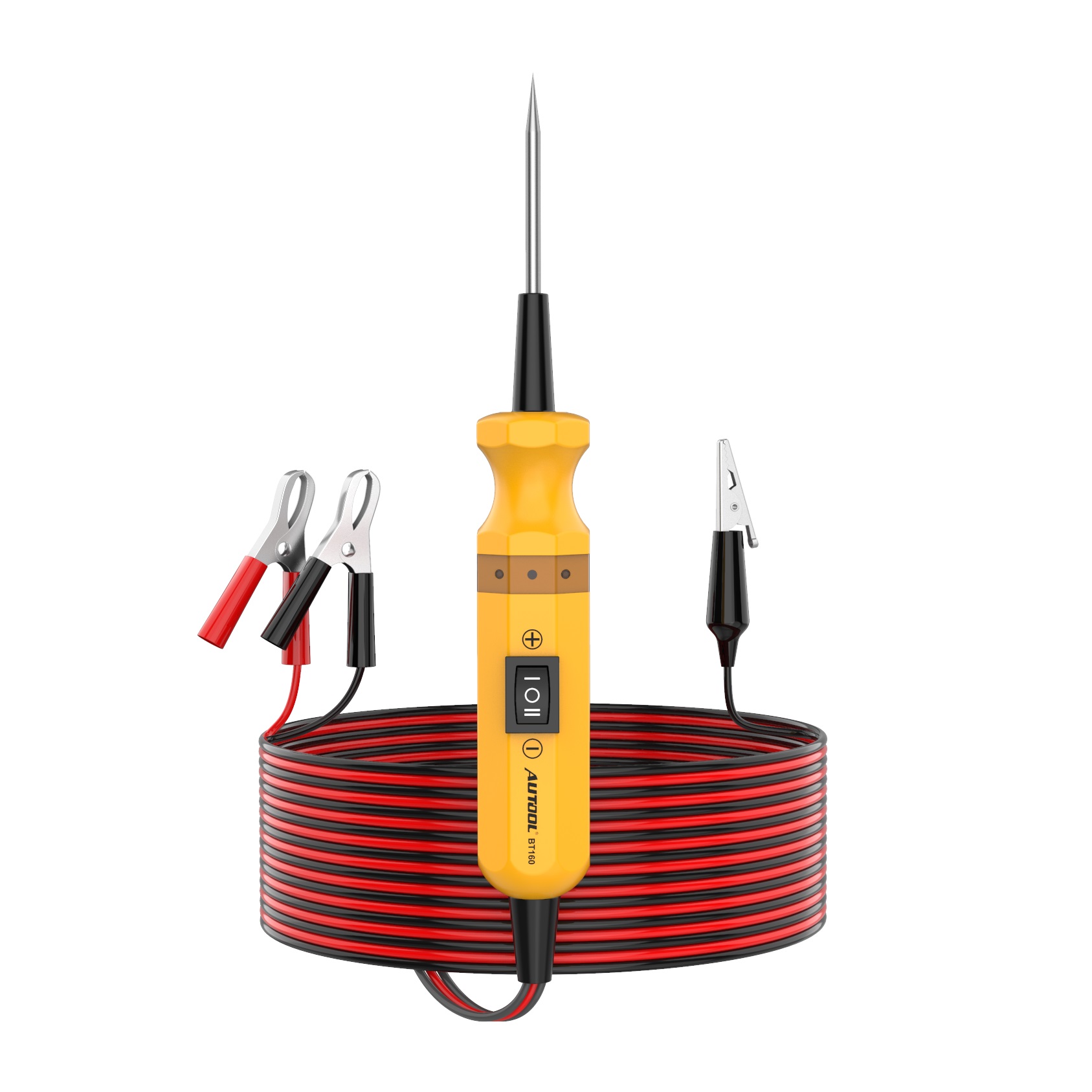
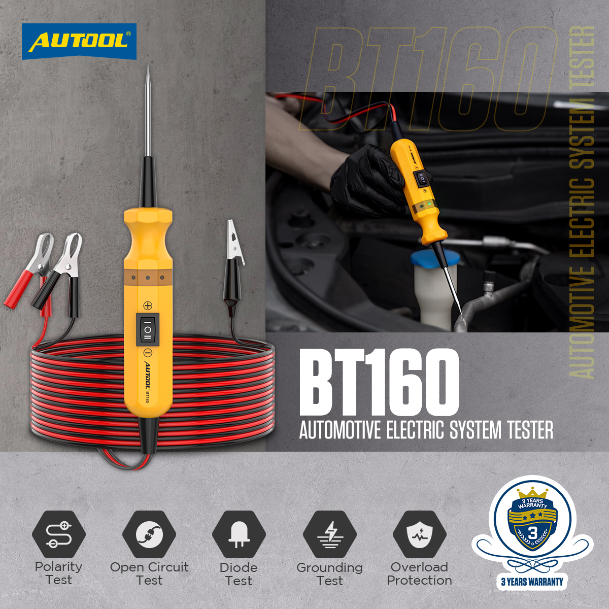
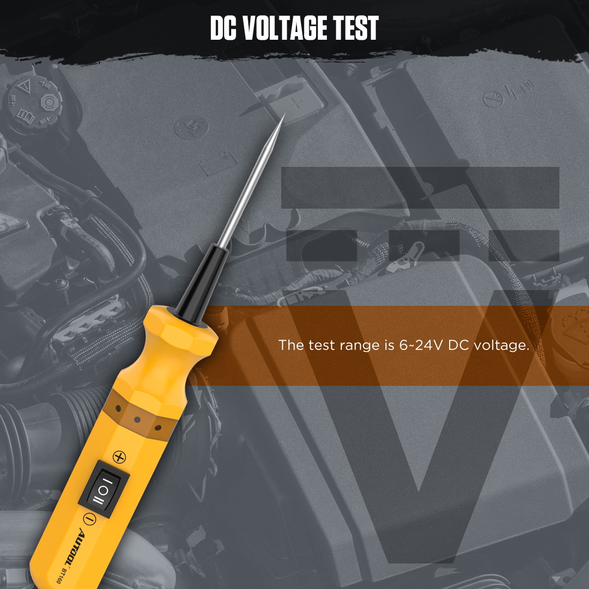
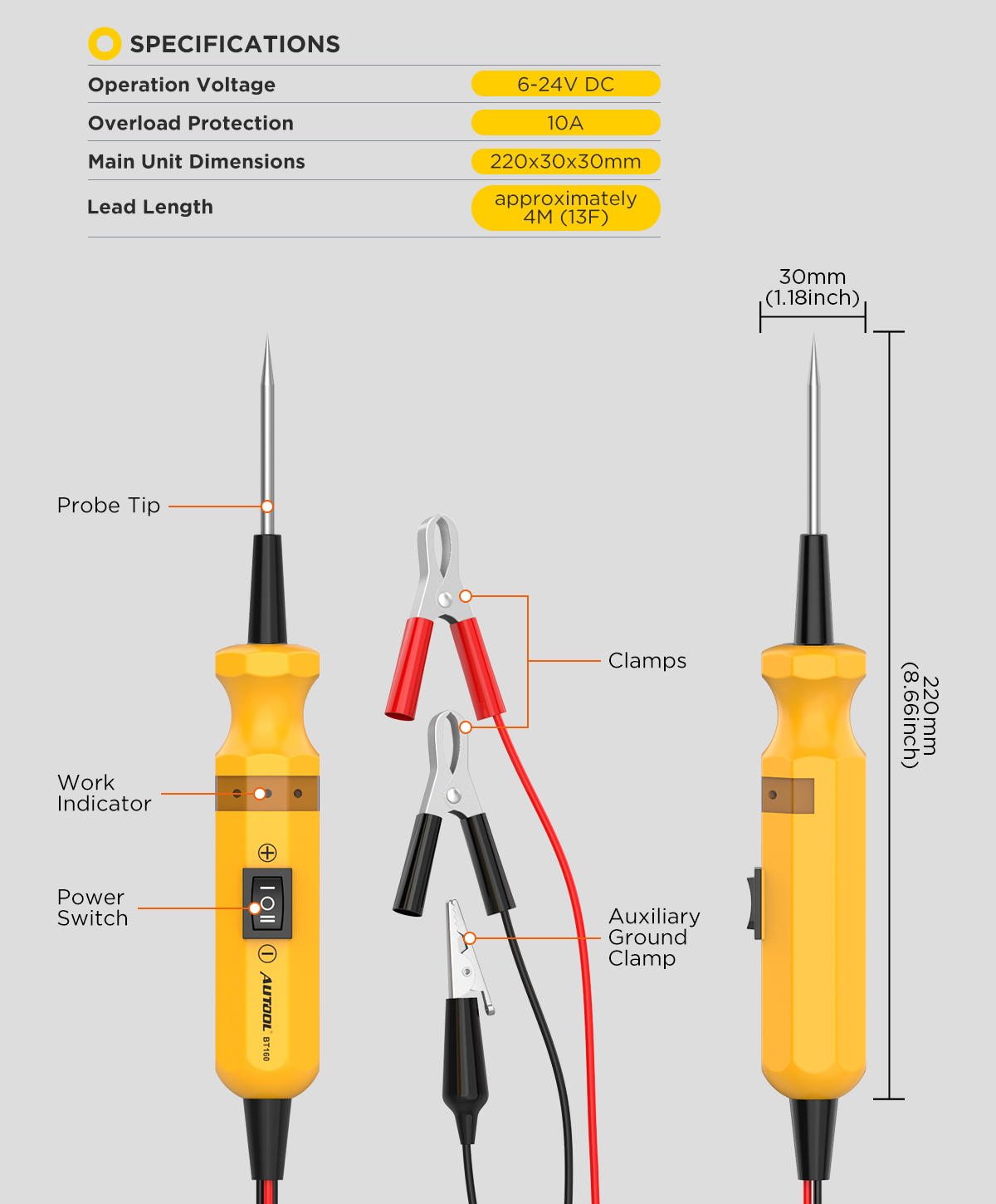
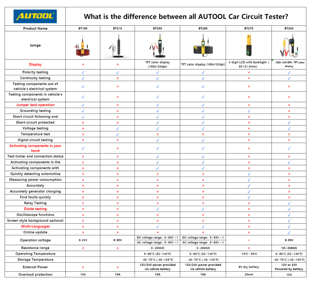
Professional Circuit Tester: Suitable for testing electrical systems with DC voltages ranging from 6V to 24V, including applications in cars, motorcycles, trucks, excavators, ships, and more.
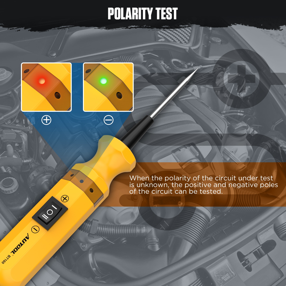
Quick Polarity Identification: When the metal probe touches the positive terminal, the LED light turns red; when it touches the negative terminal, the LED light turns green.
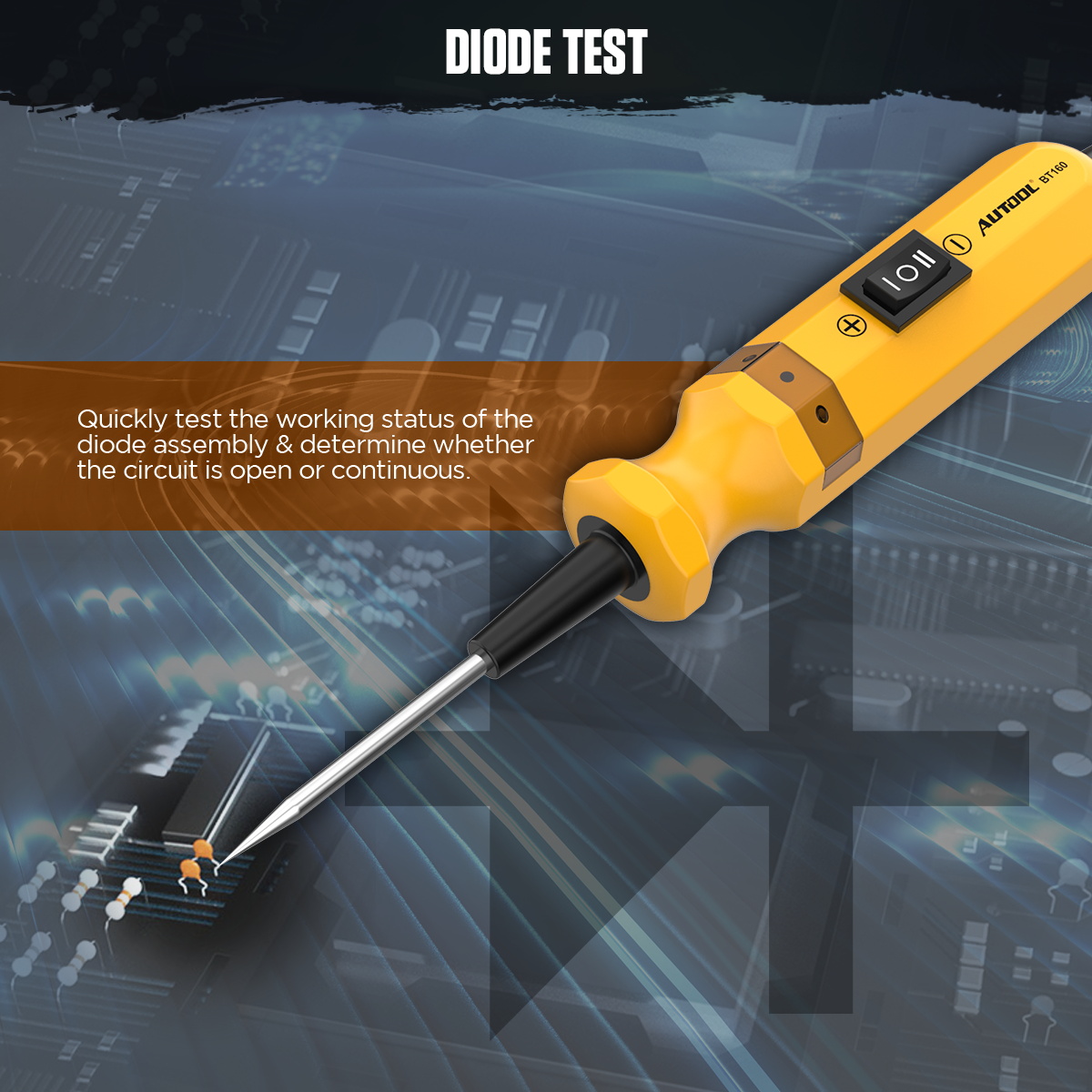
Multi-function Testing: Supports polarity identification, continuity testing, circuit open/closed testing, ground fault detection, circuit tracing, jumper detection, component activation, and more.
Easy Fault Detection: Capable of testing socket and cable polarity, and checking the continuity of switches, relays, headlights, diodes, fuses, wires, and circuits.
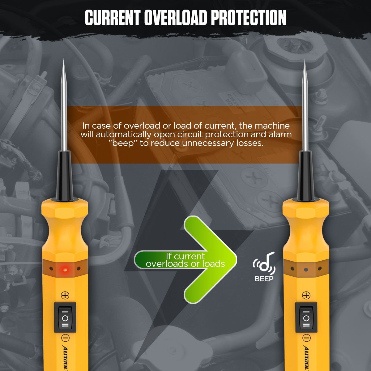
Overload Power-Off Protection: When the measured voltage exceeds 24V or the current exceeds 10A, the circuit tester activates the power-off protection and emits a beep warning.
Premium Materials: The circuit tester is made from high-insulation materials and is certified with China Compulsory Certification (CCC), ensuring it is safe and reliable with no leakage.
Highly Sensitive Probe: The probe is fine, durable, and wear-resistant, allowing easy insertion into hard-to-reach automotive circuits.
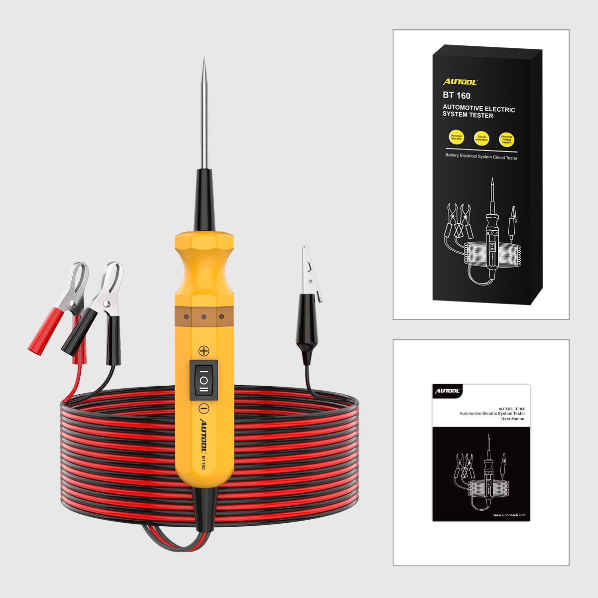
4-meter (13 ft) Test Lead: Convenient for testing, allowing easy access to various parts of the vehicle for inspection.
Operating Instruction
Polarity Test
1. Unfasten the test leads of the automotive electrical tester.
2. Connect the red clip to the positive terminal of the vehicle battery and the black clip to the negative terminal.
3. Connect the tip of the test probe to a test point with unknown polarity. If the LED on the tester lights up red, it indicates that the test point has a positive voltage. If the LED lights up green, it indicates that the test point has a negative voltage.
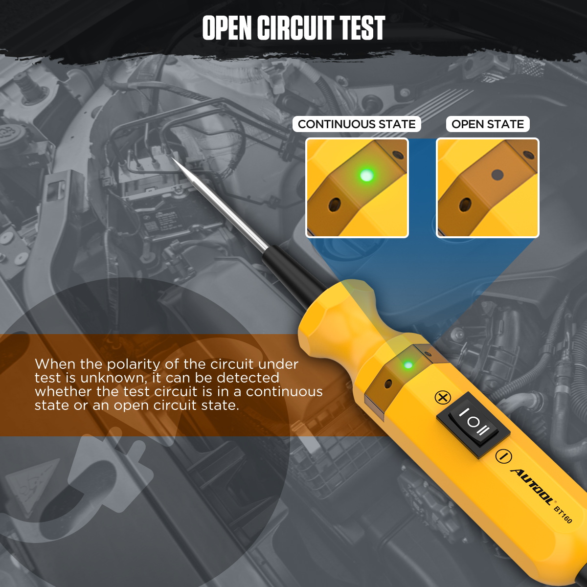
Continuity Test
1. Unfasten the test leads of the automotive electrical tester.
2. Connect the red clip to the positive terminal of the battery, and the black clip to the negative terminal of the battery.
3. Attach the auxiliary grounding clip on the tester to one end of the wire being tested. Use the probe to touch the other end of the wire. If the LED on the tester lights up green, it indicates that the wire is in a continuous state. If the LED does not light up green, it indicates that the wire is broken.
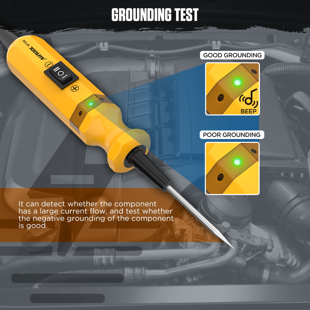
Ground Fault Test
1. Unfasten the test leads of the automotive electrical tester.
2. Connect the red clip to the positive terminal of the battery, and the black clip to the negative terminal of the battery.
3. Press the “-” key on the tester, at which point the LED on the tester will light up red, indicating the metal probe is outputting positive voltage.
4. Contact the probe with the negative terminal (negative grounding point) of the component, as close to the component’s end as possible.
5. When grounding is intact, the LED on the tester turns green and emits a beeping sound.
Circuit Tracing Test
1. Unfasten the test leads of the automotive electrical tester.
2. Connect the red clip to the positive terminal of the battery, and the black clip to the negative terminal of the battery.
3. Press the “-” key on the tester, at which point the LED on the tester will light up red, indicating the metal probe is outputting positive voltage.
4. Remove the faulty fuse from the fuse box and begin tracing from the load side of the fuse socket, using a quick tapping motion to contact the circuit points.
5. If the tester LED turns green and emits a beeping sound, it indicates that there is a short circuit or an overloaded component in the current circuit.
6. Based on the color or wire code information of the measured circuit, trace the wire harness or cable to locate the next node position.
7. Disconnect the connection at that node and use the same quick tapping method to contact the points before and after the node in the circuit.
8. Confirm the direction of the problem and continue tracing. If a component is encountered, test it separately to ensure it is functioning correctly. Continue tracing until reaching the end of the circuit to identify and eliminate short-circuit location or overloaded components.