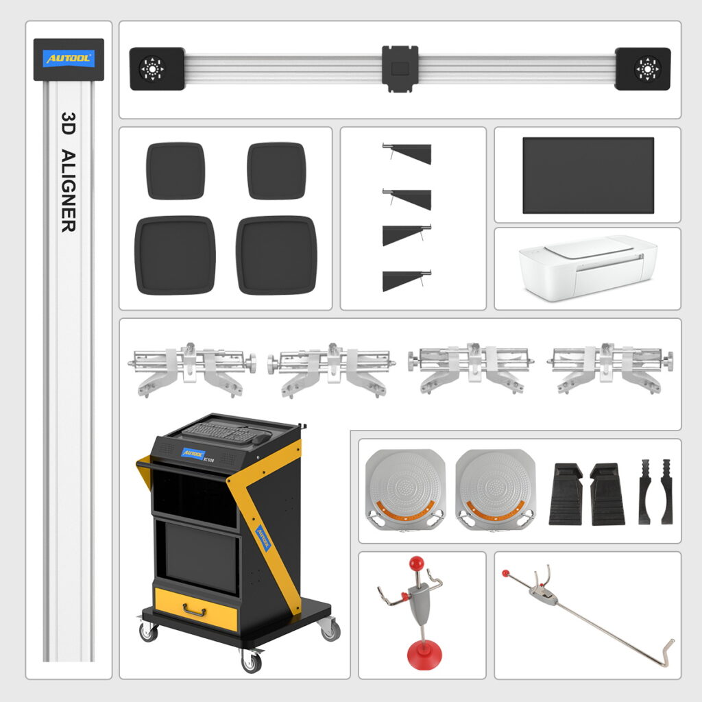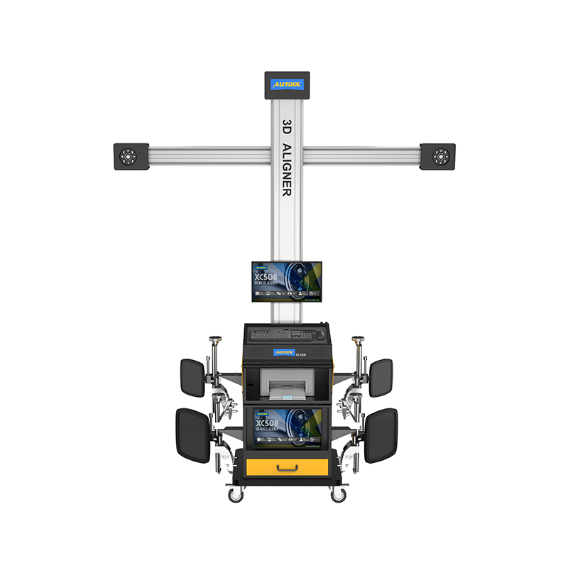
XC508 3D Wheel Aligner Machine
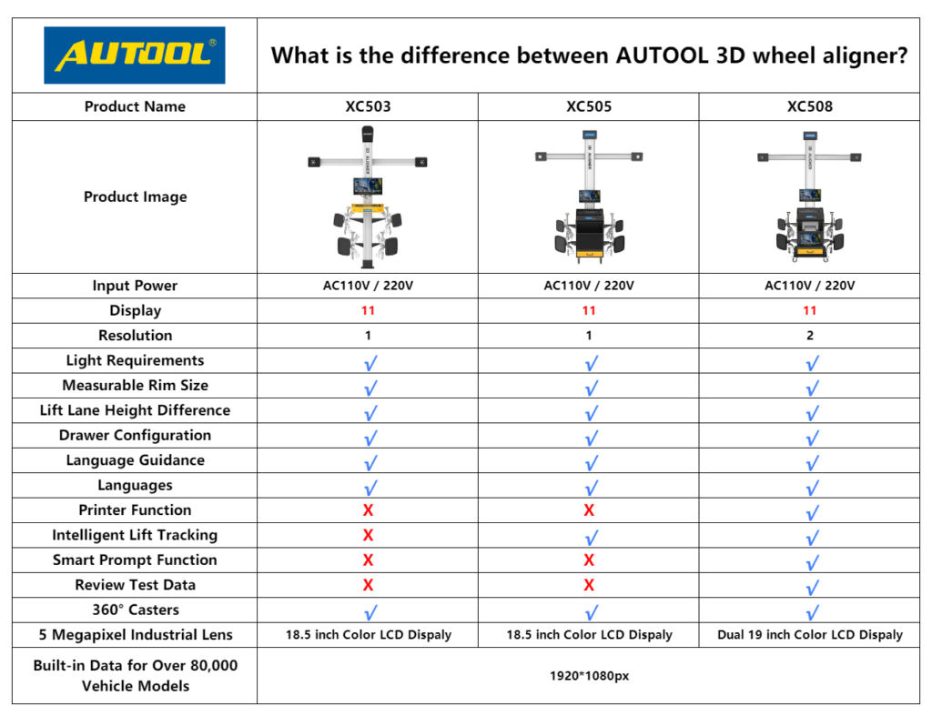
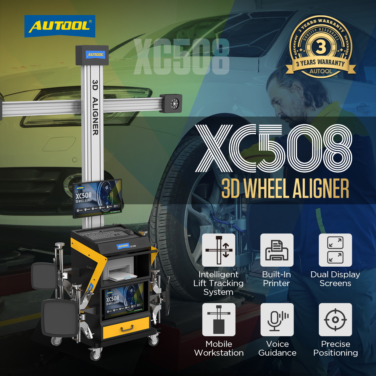
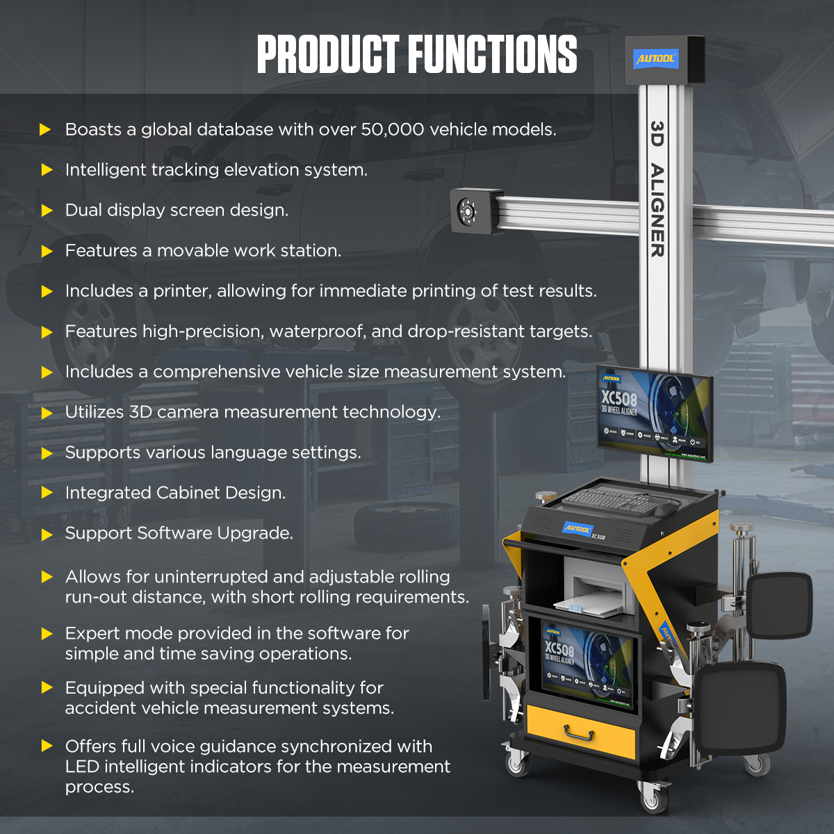
The AUTOOL XC508 3D Wheel Aligner utilizes advanced 3D camera measurement technology with 5-megapixel HD cameras, enabling precise wheel alignment without the need for camera movement. It supports over 100 vehicle brands and more than 50,000 vehicle models. Featuring high-precision, waterproof, and shock-resistant targets, it requires no calibration. Additionally, the equipment offers voice and LED guidance, full vehicle dimension measurement, intelligent tracking, dual displays, and a built-in printer.


The wheel aligner is a equipment used to inspect and adjust a vehicle’s wheel alignment parameters. Its working principle primarily includes the following aspects: utilizing triangulation measurement, sensor-based measurement methods (such as photoelectric sensors, angle sensors, and camera image processing), phototransistors and PSD measurement, as well as CCD measurement technology to determine the wheel’s angle, position, and distance. The collected raw data undergoes calibration, filtering, timing analysis, and mathematical modeling to compute wheel alignment parameters such as toe-in angle, camber angle, and caster angle. The results are then provided to the user for necessary adjustments. The process involves vehicle inspection, equipment installation and calibration, data collection, data analysis and adjustment, followed by verification of the adjusted results. By precisely measuring and adjusting wheel alignment parameters, the wheel aligner provides essential support for vehicle maintenance and servicing.
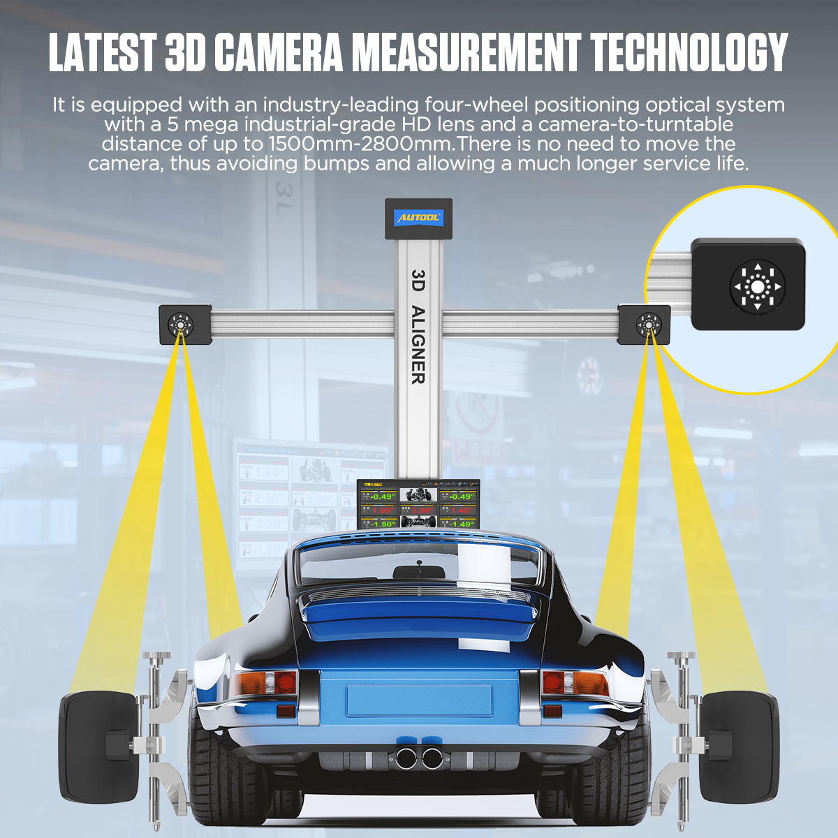
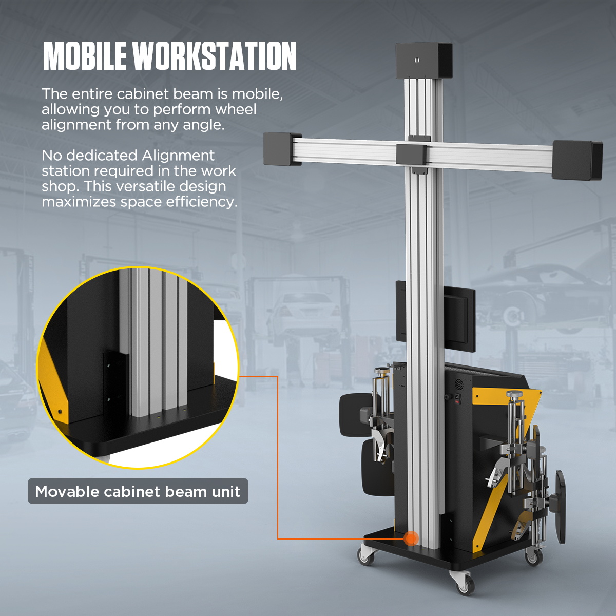
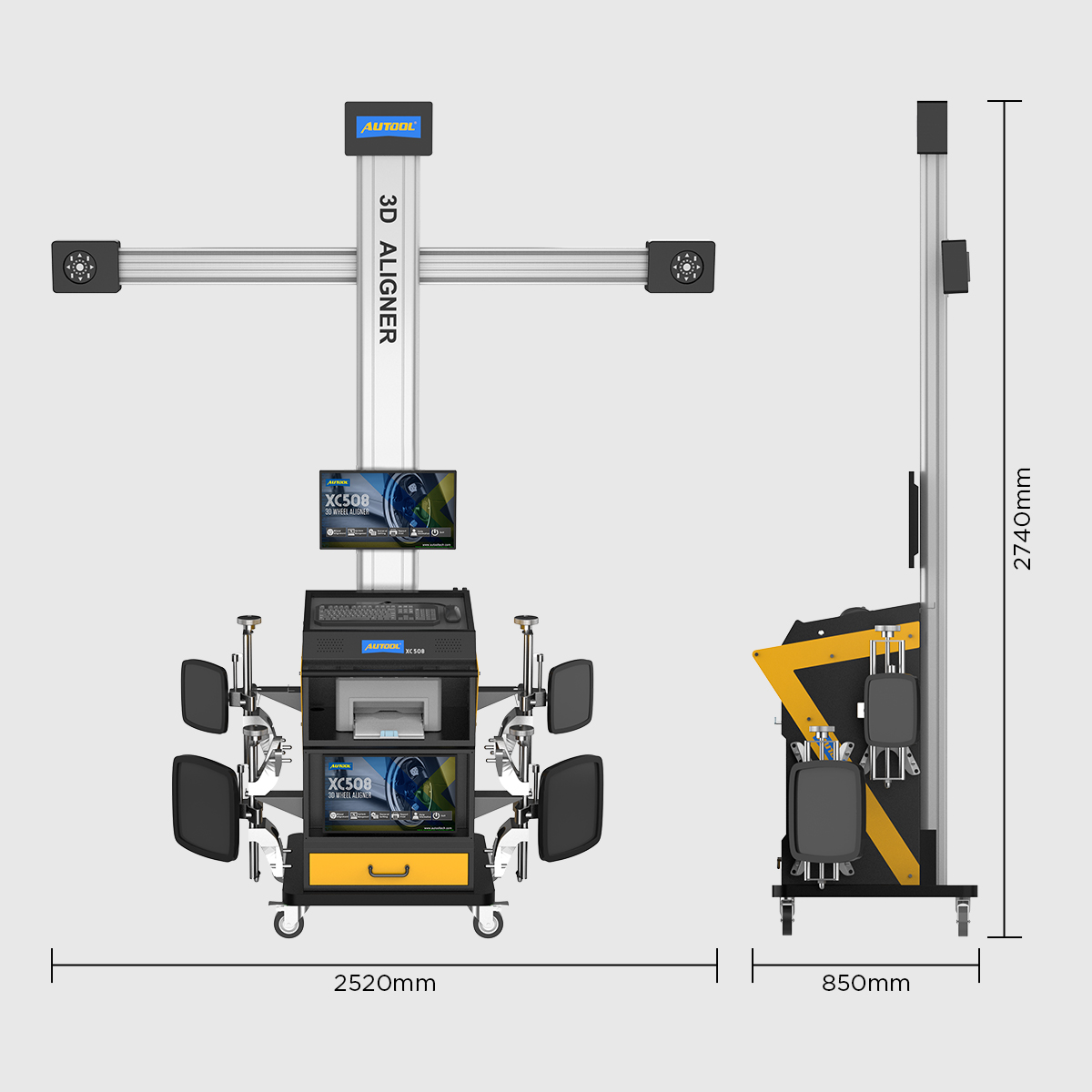
3D Camera Measurement Technology: The wheel alignment and balancing tool features an industry-leading four-wheel alignment optical system equipped with a 5-megapixel industrial-grade HD camera. The camera-to-turntable distance ranges from 1500mm to 2800mm, eliminating the need for camera movement, reducing vibrations, and extending the equipment’s lifespan.
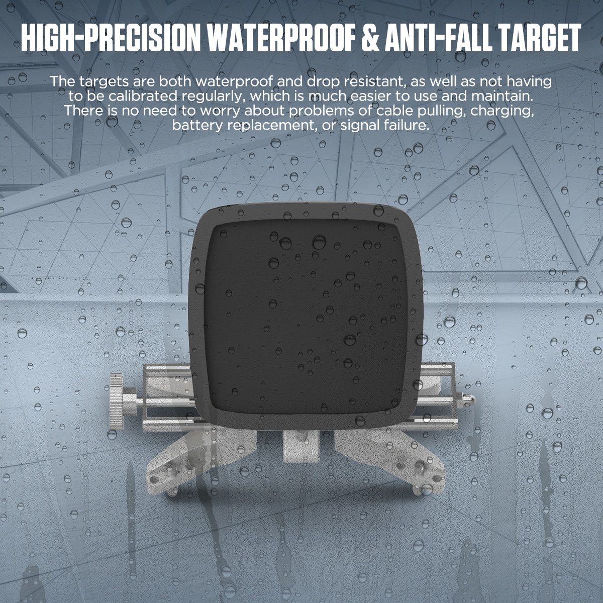
High-Precision Waterproof and Drop-Resistant Targets: Featuring an integrated design, the targets are both waterproof and drop-resistant, eliminating the need for regular calibration, making operation and maintenance more convenient.
Extensive Global Database: The XC508 3D Wheel Aligner supports over 100 automotive brands and more than 50,000 vehicle models, with the option for users to add custom models.
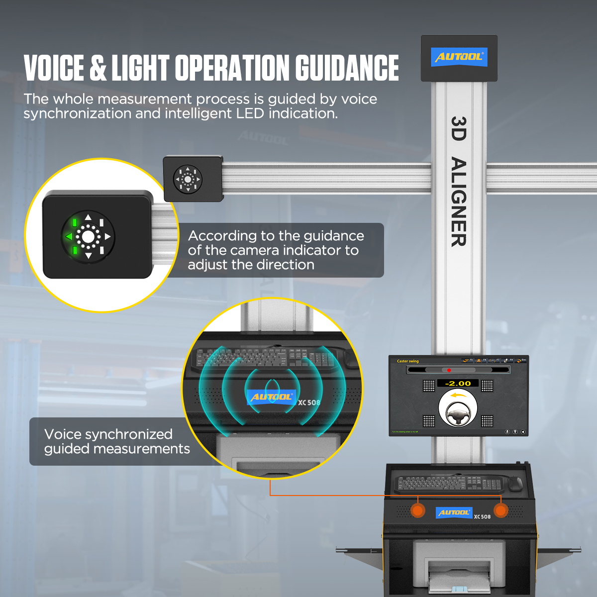
Voice and Light-Guided Operation: The entire measurement process is guided by synchronized voice prompts and intelligent LED indicators.
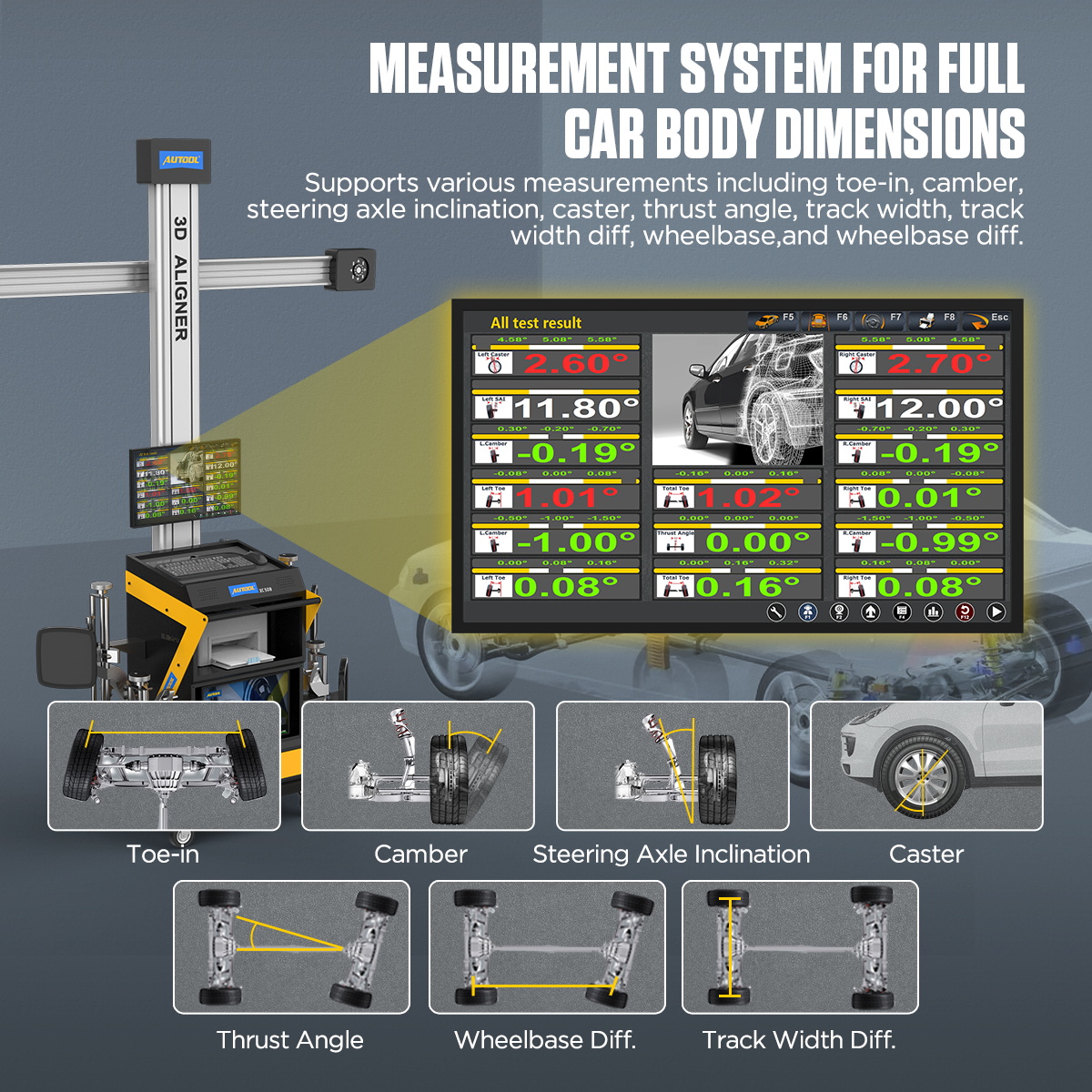
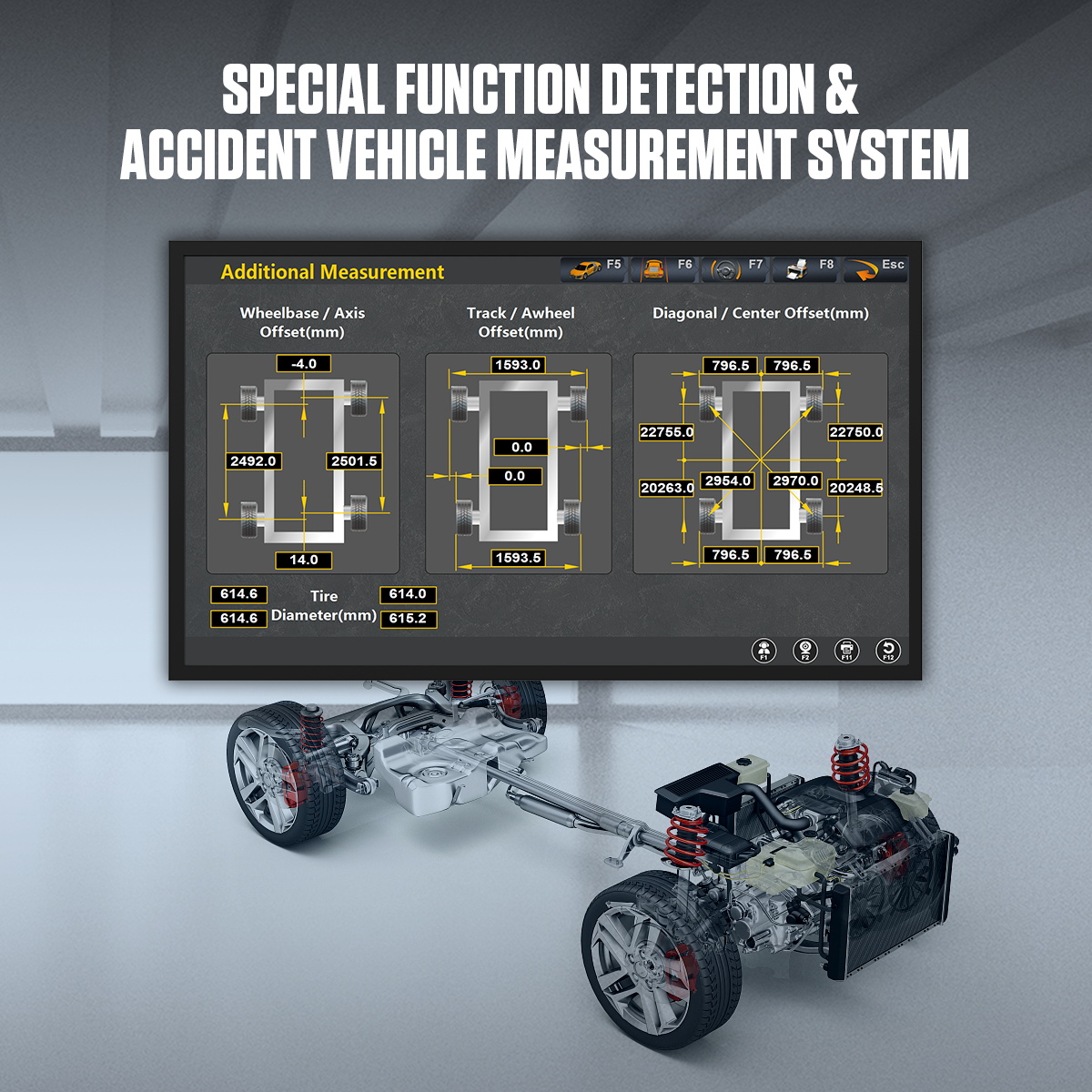
Full Vehicle Dimension Measurement System: The wheel aligner supports various measurements, including toe-in, camber angle, steering axis inclination, caster, thrust angle, track width, track width difference, wheelbase, and wheelbase difference.
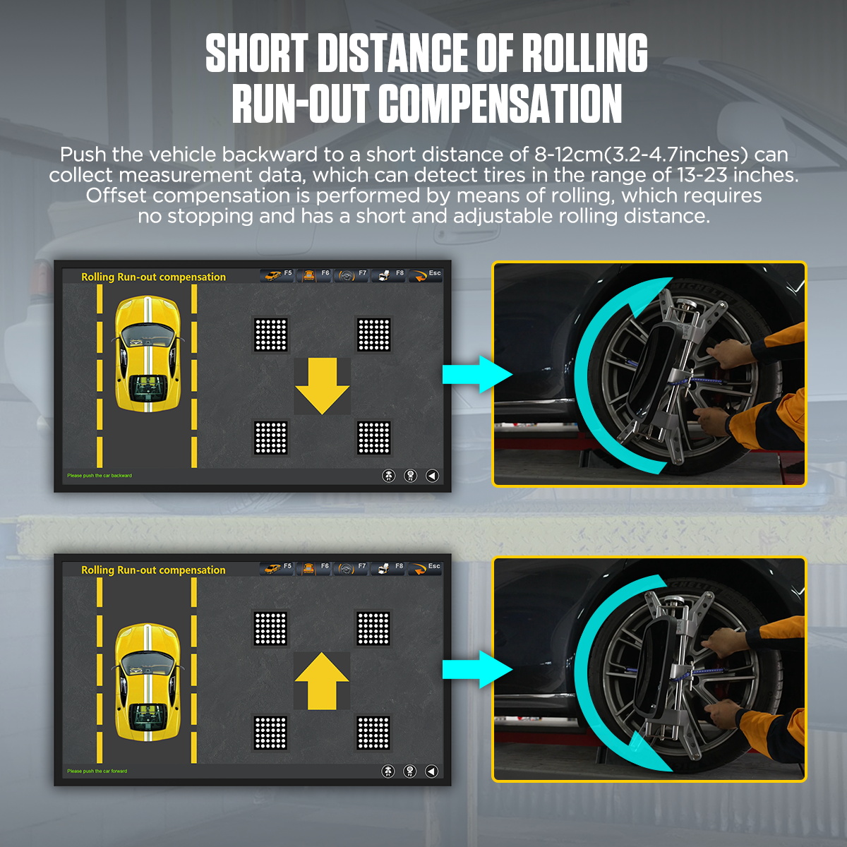
Short-Distance Rolling Deviation Compensation: By rolling the vehicle backward just 8-12 cm (3.2-4.7 inches), measurement data is collected. This system enables deviation compensation for tires ranging from 13 to 23 inches through rolling movement, eliminating the need for stopping. The rolling distance is short and easily controlled.
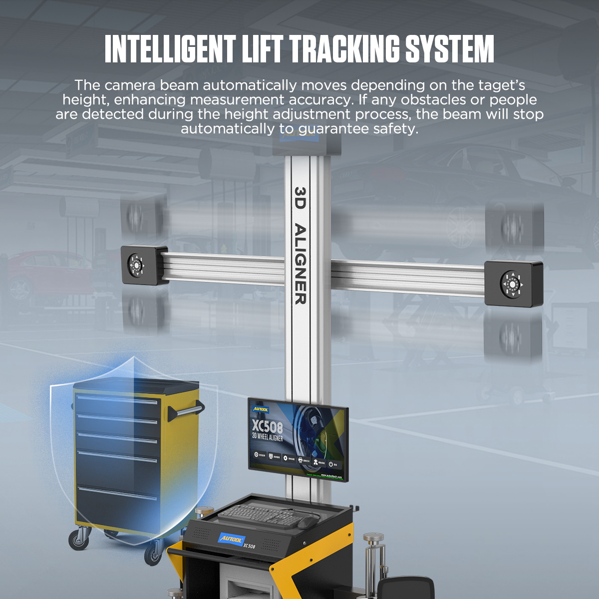
Intelligent Elevation Tracking System: The camera beam automatically adjusts according to the target height, enhancing measurement accuracy. If any obstacles or personnel are detected during height adjustment, the beam stops automatically to ensure safety.
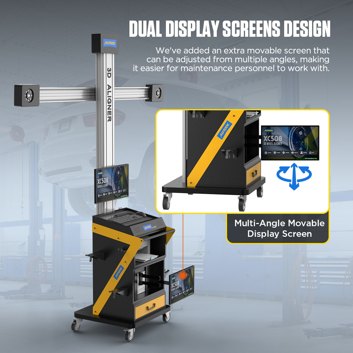
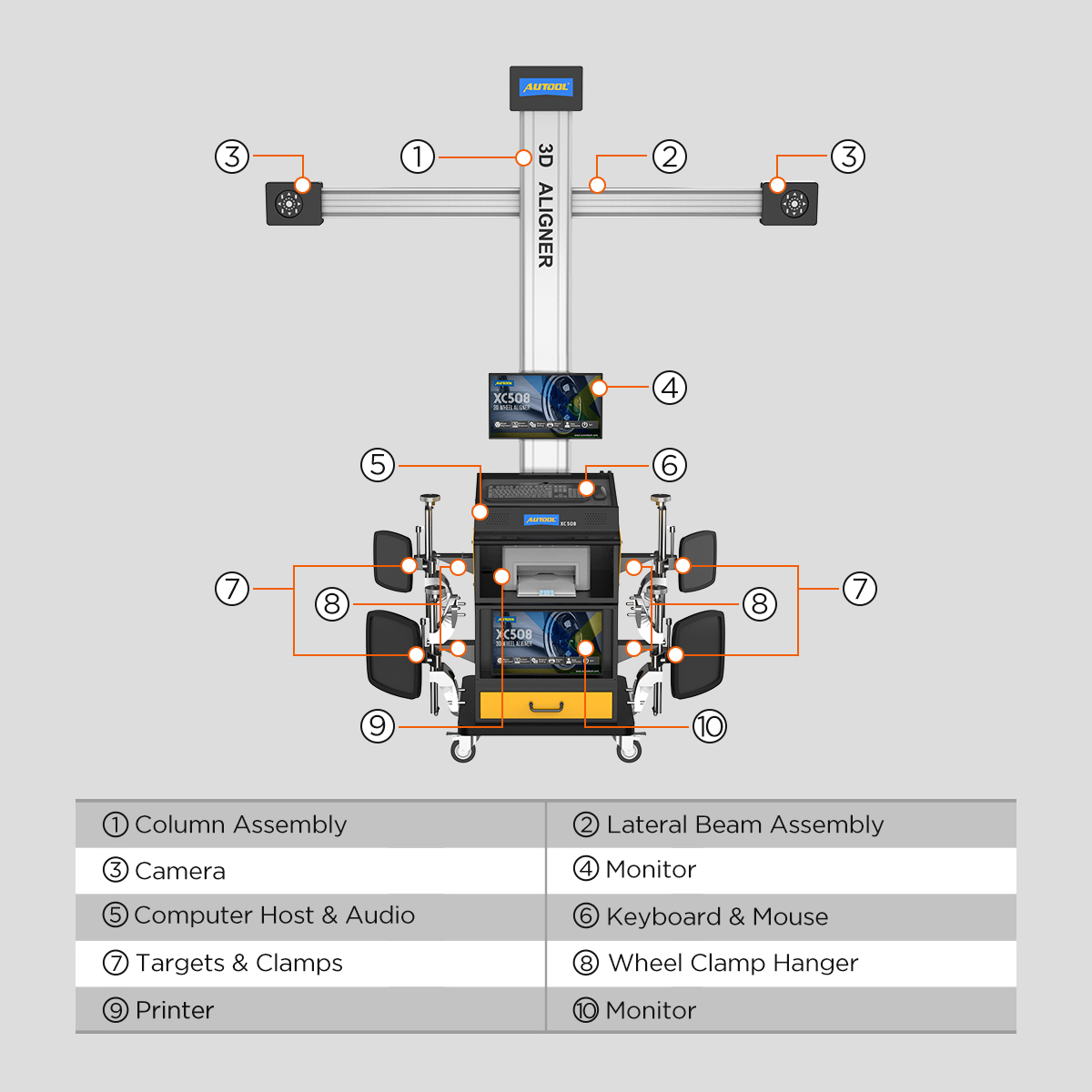
Dual Display Design: An additional adjustable screen allows for multiple viewing angles, making maintenance work more convenient.
Multilingual Support: The wheel alignment and balancing tool supports multiple languages, including English, Spanish, Russian, Arabic, Thai, Portuguese, and Chinese.
Three-year Warranty: For damages caused by non-human factors, AUTOOL promises to provide free replacement parts within three years. If you have any requests, please feel free to contact us, and we will respond promptly within 24 hours.
Check and insert the turntable and side slip plate locking pins, position the transition bridge, then slowly drive the vehicle onto the platform.
1. Position the vehicle on the platform, ensuring that the vehicle is aligned straight ahead, with the front wheels at the center of the turntable. After parking the vehicle, straighten the front wheels, turn off the ignition switch, and engage the handbrake. Place the brake blocks at the rear wheels to prevent the vehicle from sliding, then release the handbrake.
2. Carefully inspect all chassis components, including bushings, bearings, wishbones, ball joints, shock absorbers, tie rod ends, and steering components for any looseness or wear. Additionally, check the tire pressure, tire specifications, and ensure the tread pattern of both front wheels is identical, with the tread depth of the rear wheels being consistent.
3. Install the four wheel clamps and target plates onto the corresponding tires. Gently tap the clamp to ensure the jaws are securely locked in place, aligning with the outer circumference of the rim. The target plate should be perpendicular to the ground.
4. After confirming that all power cables are properly connected, turn on the main power switch of the cabinet. Once the computer starts and the system desktop is displayed, click on the alignment software icon to enter the software.
5. Click on the alignment detection option to enter the vehicle selection interface. In the vehicle selection screen, choose the corresponding manufacturer, series, and model of the vehicle, or quickly search for the vehicle data by manufacturer and model. Click “Next” to proceed to the target monitoring screen.
6. Once in the target monitoring interface, check whether the target image is displayed properly.
7. The four target images should be centered within the display area, both vertically and horizontally.
8. In the image value display area at the top left of the two images, the brightness values are displayed: the upper reference value should be between 200-240, and the lower value should be between 160-200. If the values are outside this range or too low, click the “Exposure Time Setting” button at the bottom right of the interface to enter the adjustment screen and make corrections.
9. In the image display area at the top left of the two images, the image value should end with the number 21. If it doesn’t, check the cleanliness of the target or camera lens.
10. After confirming the above, click “Next” to enter the rolling compensation interface.
11. Enter the rolling compensation interface and follow the prompts to push the vehicle for data measurement. After pushing the vehicle, the front toe-in and camber data for all four wheels will be displayed. This interface provides real-time data display. If kingpin measurements are not required, you can compare the four-wheel alignment data in this interface to diagnose any issues with the vehicle and make necessary adjustments. (Before making adjustments, remove the turntable and side slip board’s locking pins, and use the steering wheel bracket to secure the steering wheel). To test the kingpin, click “Next” to enter the kingpin measurement.
12. After entering the kingpin measurement (ensure the turntable locking pins are removed, and use the brake plate fixture to secure the brake), follow the prompts for the kingpin measurement. Once completed, the vehicle measurement data screen will automatically appear. This is a real-time display interface. In this interface, compare the four-wheel alignment data to diagnose any issues with the vehicle and make the required adjustments. (Before making adjustments, remove the turntable and side slip board’s locking pins, and use the steering wheel bracket to secure the steering wheel). After adjustments, click “Next” to enter the report printing interface.
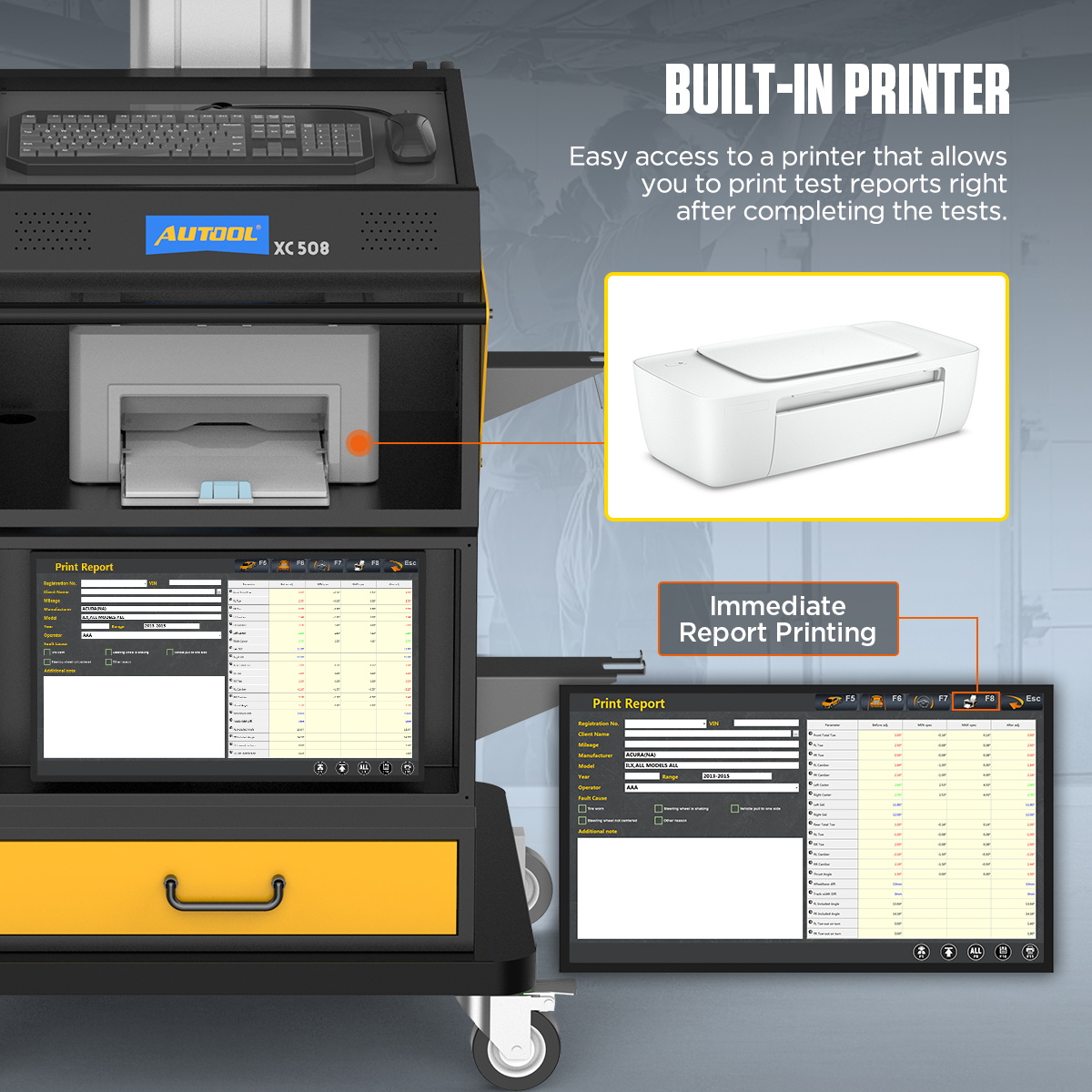
13. In the report printing interface, enter customer information such as name and license plate number as required, then save the information. If a report is needed, click the “Print” button in this interface to print the report.
14. After finishing the work, exit the measurement software system and return to the desktop, then click to shut down. Remove the wheel clamps from the vehicle and place them in the designated location. Avoid striking, forcefully colliding, or dropping them on the ground.
15. Afterward, first turn off the computer host power, and then turn off the main power supply. Drive the vehicle off the platform and clean the area.
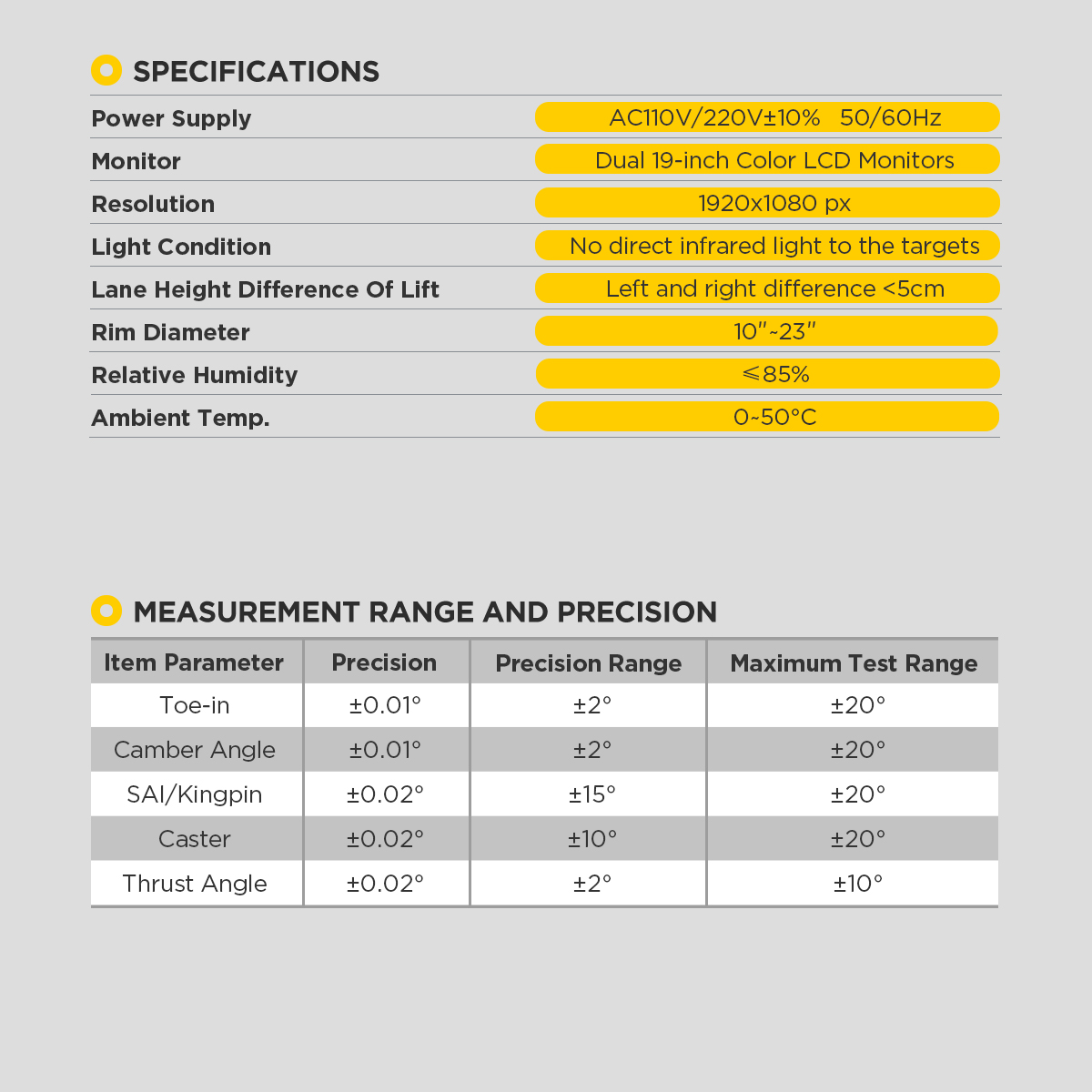
| XC508 (Table 1) | |
| Power Supply | AC110V/220V+10% 50/60HZ |
| Monitor | Dual 19-inch Color LCD Monitors |
| Resolution | 1920x1080px |
| Light Condition | No direct infrared light to the targets |
| Lane Height Difference Of Lift | Left and right difference <5cm |
| Rim Diameter | 10~23 inches |
| Relative Humidity | ≤85% |
| Ambient Temperature | 0~50°C (32~122°F) |
| XC508 (Table 2) | |||
| Item Parameter | Precision | Precision Range | Maximum Test Range |
| Toe-in | ±0.01° | ±2° | ±20° |
| Camber Angle | ±0.01° | ±2° | ±20° |
| SAI/Kingpin | ±0.02° | ±15° | ±20° |
| Caster | ±0.02° | ±10° | ±20° |
| Thrust Angle | ±0.02° | ±2° | ±10° |