image 0
image 0

XC503 3D Wheel Aligner Machine

The AUTOOL XC503 Wheel Alignment utilizes advanced 3D imaging positioning technology and body-based measurement technology to provide real-time, high-precision wheel alignment data detection, ensuring greater accuracy and stability. With professional wheel alignment measurement technology, the operation is fast and simple. It requires no workbench space and is not limited by lift platforms or space, making it suitable for various operating environments. Supported by a powerful database that can be continuously updated, it is ideal for tire shops, repair shops, and automotive 4S dealerships, offering greater versatility and broader applicability.

  • image 0
  • image 0
  • image 0
  • image 0
  • image 0
  • image 0
  • image 0
  • image 0
  • image 0
  • image 0
  • image 0
  • image 0
  • image 0
  • image 0
  • image 0
  • image 0
  • image 0
  • image 0
Working Principle

The wheel aligner is a equipment used to inspect and adjust a vehicle’s wheel alignment parameters. Its working principle primarily includes the following aspects: utilizing triangulation measurement, sensor-based measurement methods (such as photoelectric sensors, angle sensors, and camera image processing), phototransistors and PSD measurement, as well as CCD measurement technology to determine the wheel’s angle, position, and distance. The collected raw data undergoes calibration, filtering, timing analysis, and mathematical modeling to compute wheel alignment parameters such as toe-in angle, camber angle, and caster angle. The results are then provided to the user for necessary adjustments. The process involves vehicle inspection, equipment installation and calibration, data collection, data analysis and adjustment, followed by verification of the adjusted results. By precisely measuring and adjusting wheel alignment parameters, the wheel aligner provides essential support for vehicle maintenance and servicing.

AUTOOL XC503 Automotive Alignment Machine Features

High-Precision Technology: The XC503 Wheel Alignment utilizes high-precision technology to accurately receive data and signals, eliminating the hassle of wired connections, charging, battery replacements, and signal failures.

Dual Audio-Visual Display: The XC503 provides synchronized voice guidance throughout the entire operation process, along with LED intelligent display. This allows users to complete alignment operations accurately without needing to look at the computer screen. Users can rotate the vehicle forward, backward, left, or right according to the camera indicator lights, optimizing work efficiency.

Traceable and Printable Test Data: The XC503 enables traceability of test data, including detailed vehicle parameters. Additionally, the alignment machine features a printing function, allowing users to print historical data, save reports, and generate current information reports.

Cost Savings: The XC503 Automotive Alignment Machine consists of fewer components, making the system simple and highly reliable with a low failure rate. Once installed, the instrument only requires a one-time calibration, which is straightforward and does not require periodic recalibration. The alignment technology is maintenance-free, significantly reducing operational costs.

Multiple Languages: The XC503 supports various language settings, including Chinese, English, Spanish, Russian, Arabic, Thai, Portuguese, and more. With no restrictions on language settings, it offers greater convenience for users.

Expert Mode: The XC503 is equipped with an advanced calibration software system featuring an integrated expert mode. This ensures a simple and fast operation process, significantly saving valuable time. Compared to standard alignment machines, it reduces working time by more than 30%.

Fixed Column Design: The XC503 Automotive Alignment Machine features a stable column design, ensuring a safer overall structure with a modern and stylish appearance.

Three-year Warranty: For damages caused by non-human factors, AUTOOL promises to provide free replacement parts within three years. If you have any requests, please feel free to contact us, and we will respond promptly within 24 hours.

AUTOOL XC503 Wheel Alignment Machine Operation Steps
Wheel Aligner Operating Procedure

Check and insert the turntable and side slip plate locking pins, position the transition bridge, then slowly drive the vehicle onto the platform.

1. Position the vehicle on the platform, ensuring that the vehicle is aligned straight ahead, with the front wheels at the center of the turntable. After parking the vehicle, straighten the front wheels, turn off the ignition switch, and engage the handbrake. Place the brake blocks at the rear wheels to prevent the vehicle from sliding, then release the handbrake.

2. Carefully inspect all chassis components, including bushings, bearings, wishbones, ball joints, shock absorbers, tie rod ends, and steering components for any looseness or wear. Additionally, check the tire pressure, tire specifications, and ensure the tread pattern of both front wheels is identical, with the tread depth of the rear wheels being consistent.

3. Install the four wheel clamps and target plates onto the corresponding tires. Gently tap the clamp to ensure the jaws are securely locked in place, aligning with the outer circumference of the rim. The target plate should be perpendicular to the ground.

4. After confirming that all power cables are properly connected, turn on the main power switch of the cabinet. Once the computer starts and the system desktop is displayed, click on the alignment software icon to enter the software.

5. Click on the alignment detection option to enter the vehicle selection interface. In the vehicle selection screen, choose the corresponding manufacturer, series, and model of the vehicle, or quickly search for the vehicle data by manufacturer and model. Click “Next” to proceed to the target monitoring screen.

6. Once in the target monitoring interface, check whether the target image is displayed properly.

7. The four target images should be centered within the display area, both vertically and horizontally.

8. In the image value display area at the top left of the two images, the brightness values are displayed: the upper reference value should be between 200-240, and the lower value should be between 160-200. If the values are outside this range or too low, click the “Exposure Time Setting” button at the bottom right of the interface to enter the adjustment screen and make corrections.

9. In the image display area at the top left of the two images, the image value should end with the number 21. If it doesn’t, check the cleanliness of the target or camera lens.

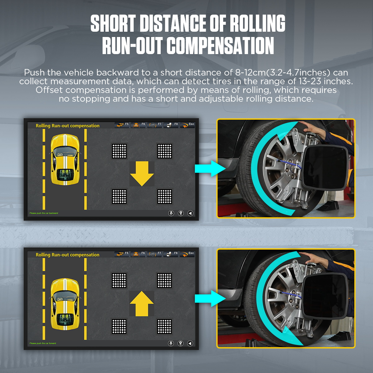
10. After confirming the above, click “Next” to enter the rolling compensation interface.

11. Enter the rolling compensation interface and follow the prompts to push the vehicle for data measurement. After pushing the vehicle, the front toe-in and camber data for all four wheels will be displayed. This interface provides real-time data display. If kingpin measurements are not required, you can compare the four-wheel alignment data in this interface to diagnose any issues with the vehicle and make necessary adjustments. (Before making adjustments, remove the turntable and side slip board’s locking pins, and use the steering wheel bracket to secure the steering wheel). To test the kingpin, click “Next” to enter the kingpin measurement.

12. After entering the kingpin measurement (ensure the turntable locking pins are removed, and use the brake plate fixture to secure the brake), follow the prompts for the kingpin measurement. Once completed, the vehicle measurement data screen will automatically appear. This is a real-time display interface. In this interface, compare the four-wheel alignment data to diagnose any issues with the vehicle and make the required adjustments. (Before making adjustments, remove the turntable and side slip board’s locking pins, and use the steering wheel bracket to secure the steering wheel). After adjustments, click “Next” to enter the report printing interface.

13. In the report printing interface, enter customer information such as name and license plate number as required, then save the information. If a report is needed, click the “Print” button in this interface to print the report.

14. After finishing the work, exit the measurement software system and return to the desktop, then click to shut down. Remove the wheel clamps from the vehicle and place them in the designated location. Avoid striking, forcefully colliding, or dropping them on the ground.

15. Afterward, first turn off the computer host power, and then turn off the main power supply. Drive the vehicle off the platform and clean the area.

XC503 (Table 1)
Power Supply AC110V/220V+10% 50/60HZ
Monitor 18.5 inch color monitor
Resolution 1920x1080px
Light Condition No direct infrared light to the targets
Lane Height Difference Of Lift Left and right difference <5cm
Rim Diameter 10~23 inches
Relative Humidity ≤85%
Ambient Temp. 0~50°C (32~122°F)
XC503 (Table 2)
Item Parameter Precision Precision Range Maximum Test Range
Toe-in ±0.01° ±2° ±20°
Camber Angle ±0.01° ±2° ±20°
SAI/Kingpin ±0.02° ±15° ±20°
Caster ±0.02° ±10° ±20°
Thrust Angle ±0.02° ±2° ±10°

滚动至顶部
×