Working Principle
The AUTOOL BT280 electrical circuit system tester uses electromagnetic induction to detect voltage signals. When the device’s metal probe makes contact with the circuit, its built-in highly sensitive sensing element detects the alternating magnetic field around the circuit. If current flows through the circuit, the LED indicator on the device immediately lights up, providing you with intuitive and accurate electrode properties.
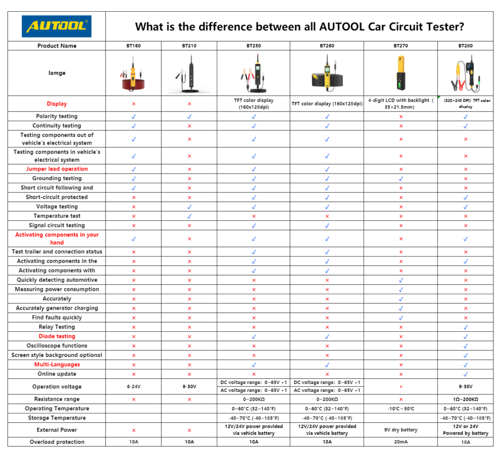
Features
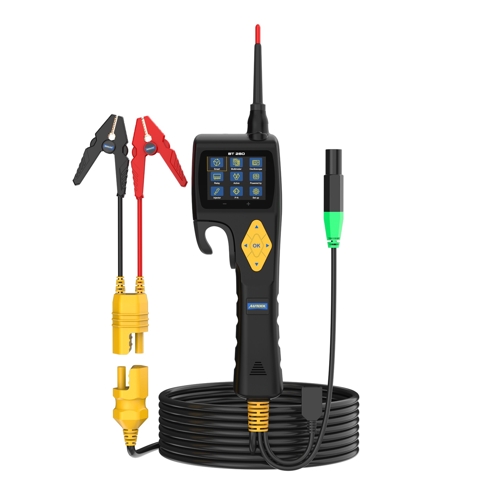
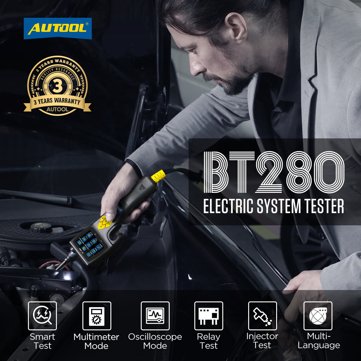
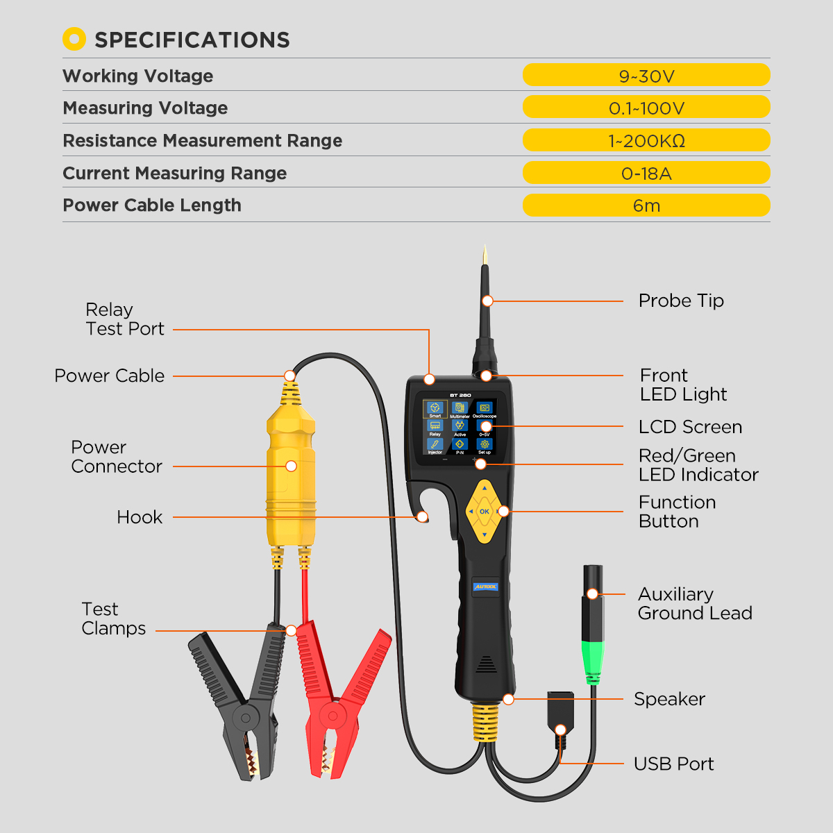
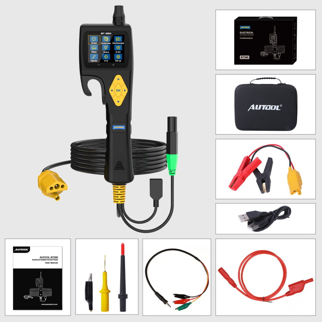
Professional circuit tester: Powered by the car battery, no additional batteries or cables are needed. Suitable for various types of vehicles, including cars, motorcycles, trucks, RVs, excavators, ships, etc. Easily locates issues such as circuit breaks, continuity, and short circuits.
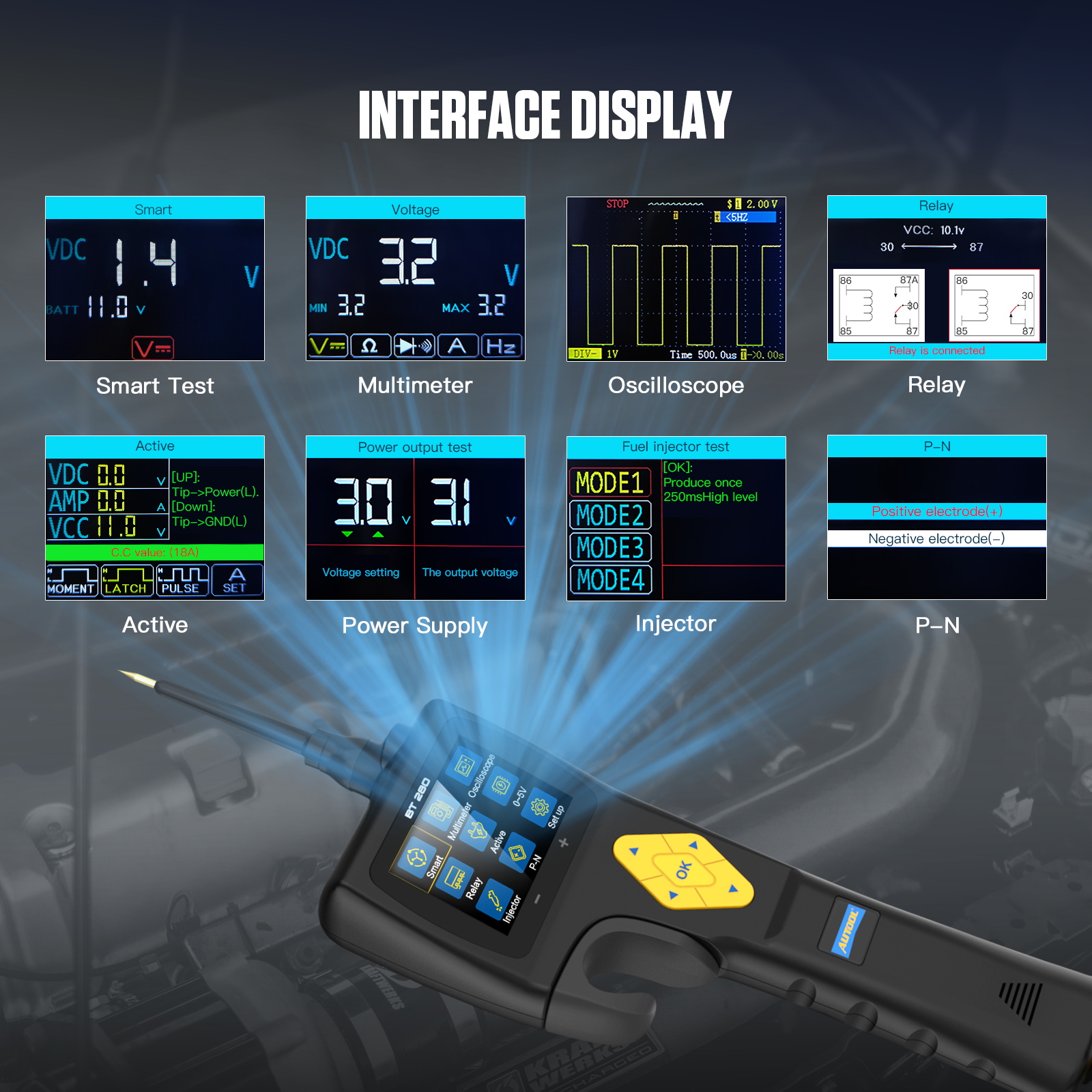
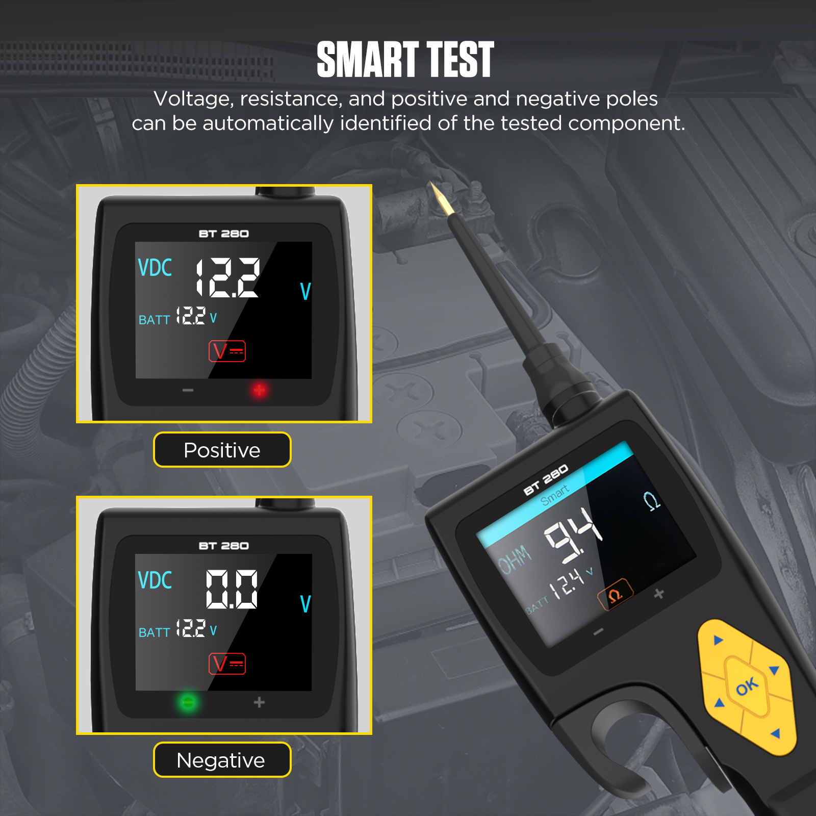
Smart detection mode: Automatically identifies voltage and resistance signals, accurately displaying the voltage, resistance, and electrode properties of the tested component on the HD display. When the LED lights up red, it indicates the positive terminal; when the LED lights up green, it indicates the negative terminal.
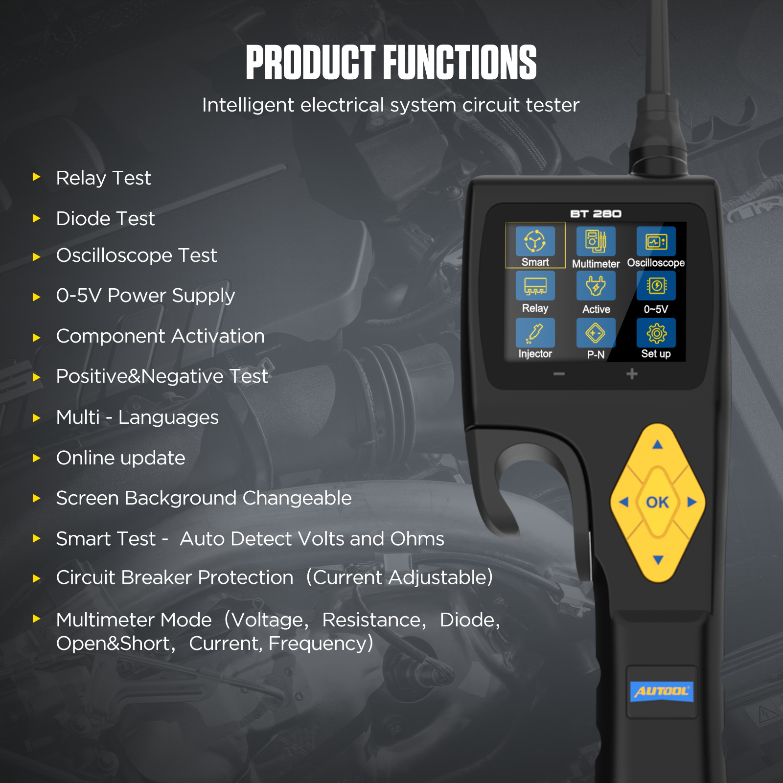
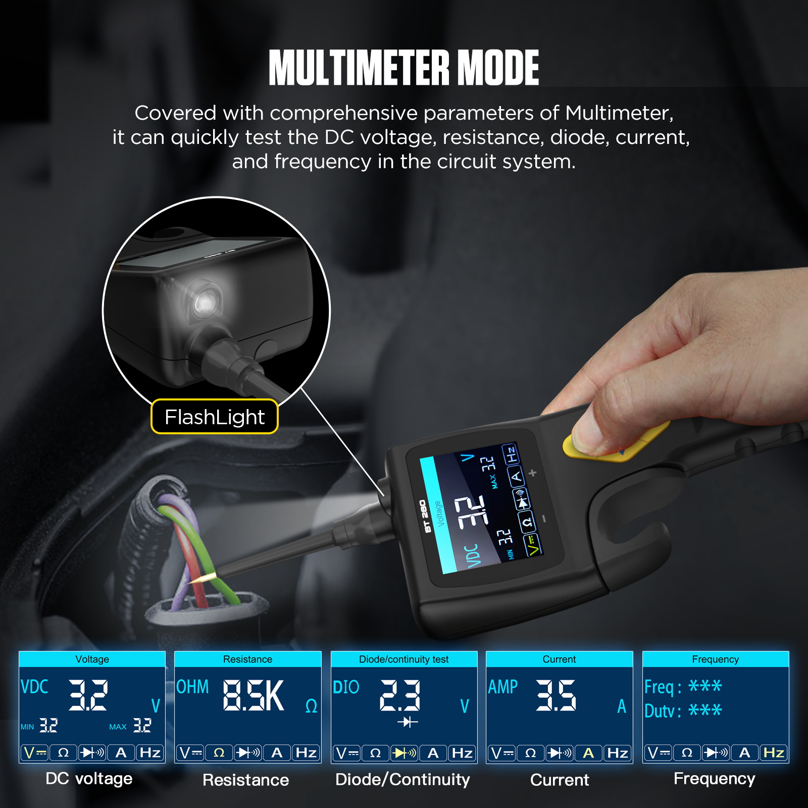
Multimeter function: The BT280 electrical circuit system tester can perform all the functions of an on-board multimeter, measuring voltage, resistance, diodes, current, and frequency. By switching to diode mode, it can test circuit continuity for car door switches, electrical wiring, light switches, faulty sockets, fuses, and more.
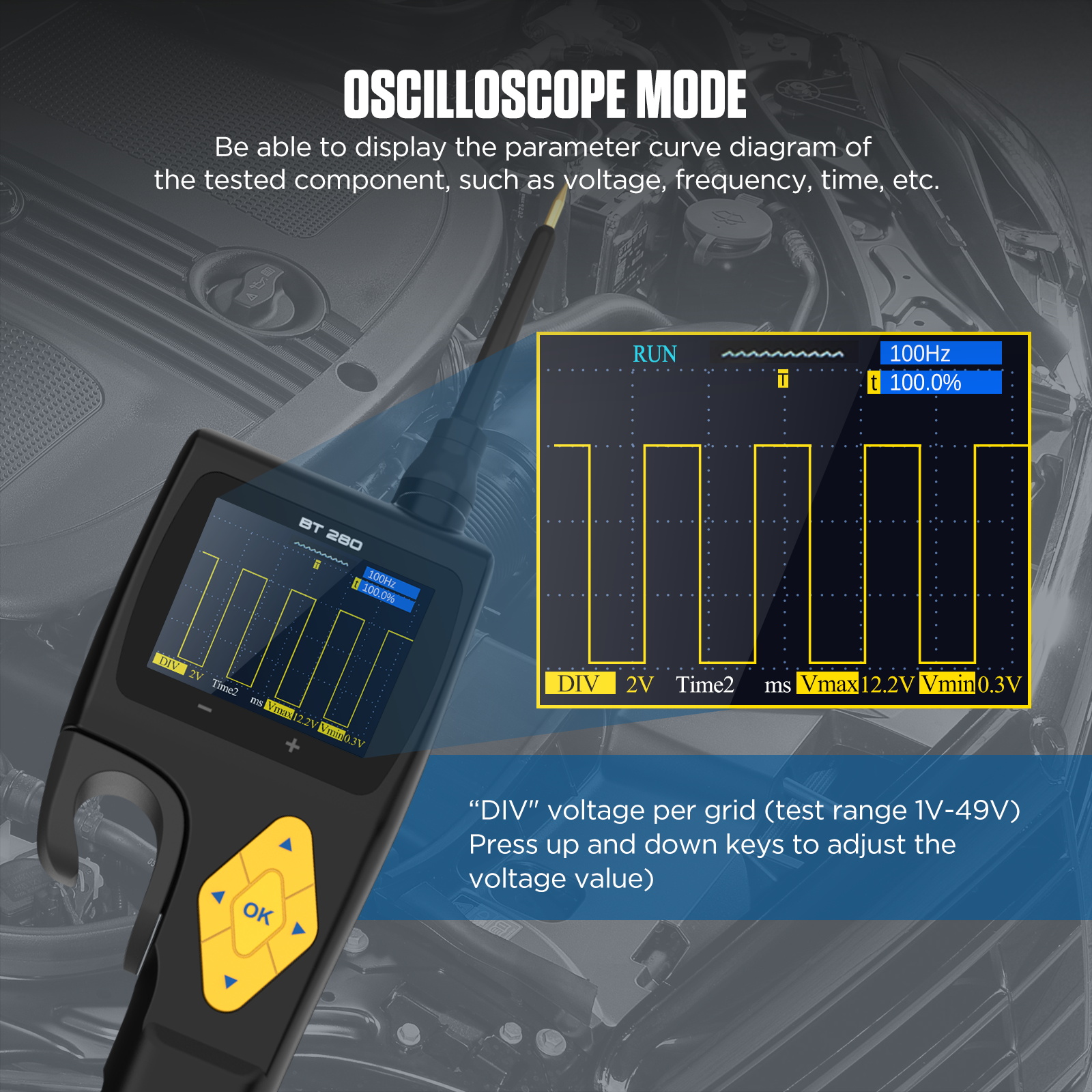
Oscilloscope function: Supports setting sampling time intervals and visually displays parameters such as signal waveform amplitude, shape, and test frequency, enabling quick identification of fault points.
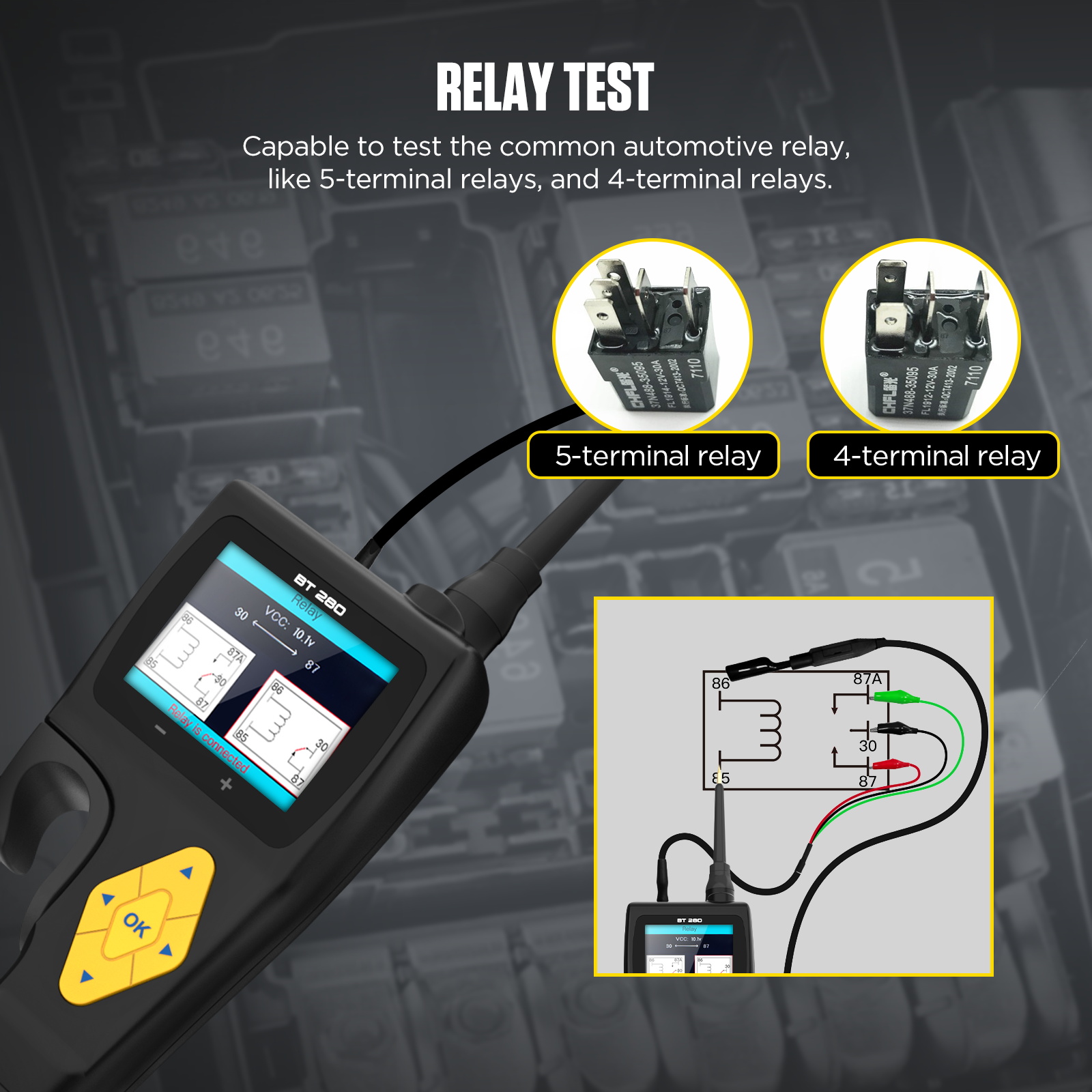
Relay function: Accurately tests various common relays in electrical systems, including four-pin and five-pin relays.
Component activation function: Offers three activation modes—instant activation, lock activation, and pulse activation—to send activation signals to the tested components, ensuring proper operation of automotive lights, motors, and other electrical tools, completing continuity or disconnection. (To avoid damaging components, please refer to the component specifications and parameters to set the overload current value.)
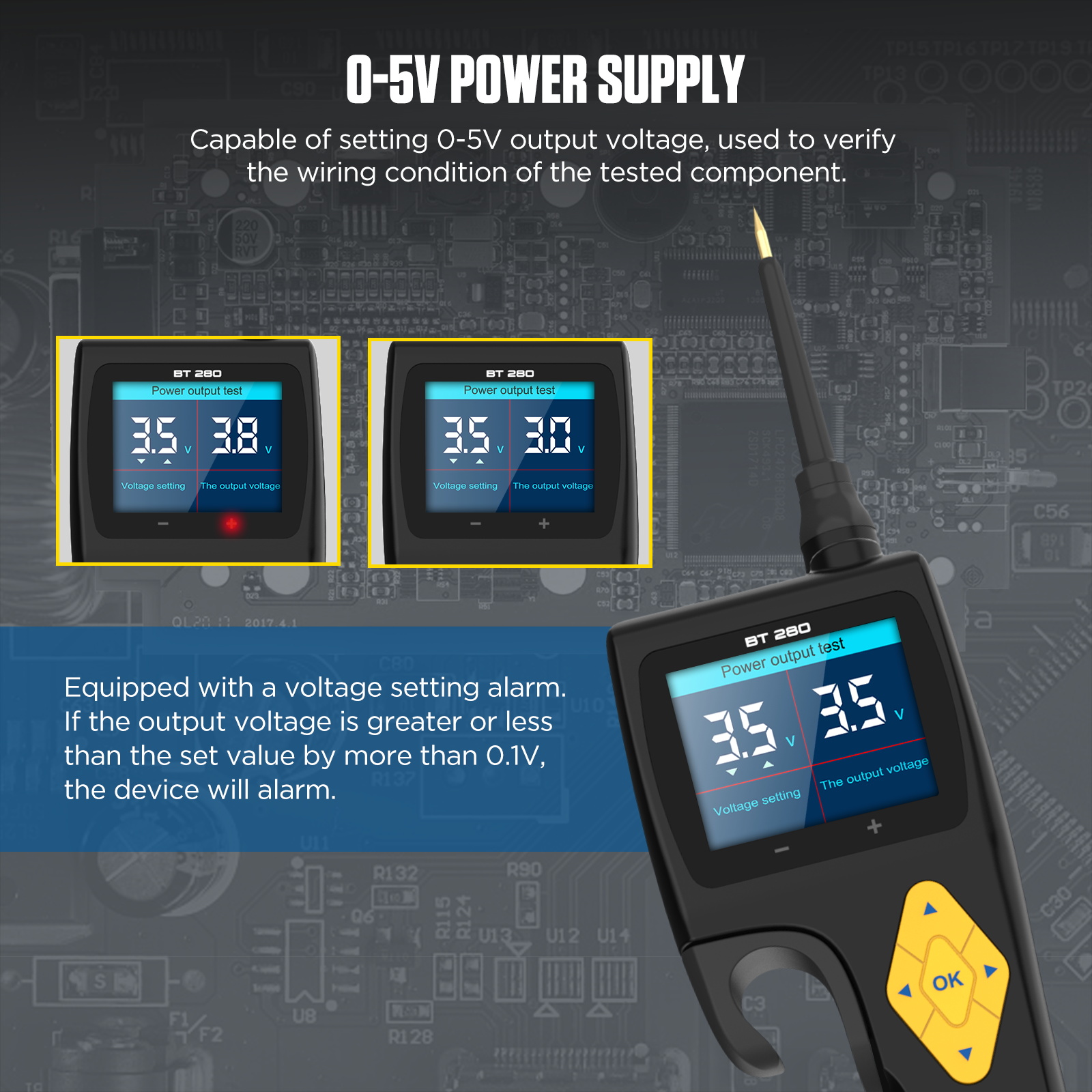
Power supply function: Allows setting of 0-5V voltage output with a current limit of 100mA, simulating output voltage to check ECU/ECM wiring issues.
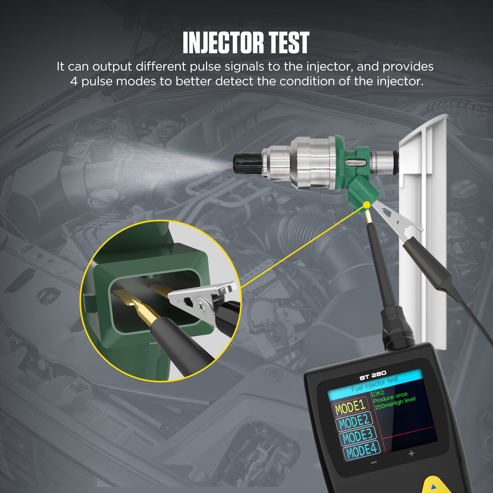
Fuel injector testing: The BT280 electrical circuit system tester offers 4 pulse signal modes, capable of outputting different pulse signals to the injector.
2.4-inch HD color display: Features a backlight design, allowing use in both dim and bright environments, clearly displaying the voltage, frequency, time, and other parameter curves of the tested component.
14 language options: English, German, Russian, French, Thai, Polish, Vietnamese, Spanish, Portuguese, Arabic, Filipino, Italian, Malaysian, Indonesian.
Dual safety protection design: The automotive circuit tester is equipped with a built-in 20-amp fuse. In the event of an overload or short circuit, it automatically cuts off the power to protect both the device and the vehicle’s safety.
Operating Instructions
Voltage/Resistance/Polarity Testing (Automatically detects voltage and resistance, no setup required)
1. Connect the red clip to the positive terminal of the vehicle battery and the black clip to the negative terminal.
2. Select the smart testing mode and connect the auxiliary grounding lead to the vehicle’s ground cable.
3. Touch the probe tip of the circuit tester to the test point. If the screen displays the present voltage value and the LED lights up red, it indicates that the contact point is the positive voltage.
4. If the screen displays the present voltage value and the LED lights up green, it indicates that the contact point is the negative voltage.
Relay Test
Connect the red clip to the positive terminal of the vehicle battery and the black clip to the negative terminal.
1. Select the relay mode and connect the relay test wire.
2. Connect the black wire to relay terminal 30.
3. Connect the green wire to relay terminal 87A (LED lights up green).
4. Connect the red wire to relay terminal 87.
5. Connect the auxiliary grounding wire (negative of the circuit tester) to terminal 86.
6. Connect the circuit tester probe to relay terminal 85.
7. Press the up button to trigger the test (red indicator light turns on, green indicator light turns off).
8. Release the button (red indicator light turns off, green indicator light turns on).
9. The circuit tester screen displays the relay test results.
Fuel Injector Test
1. Turn off the engine.
2. Connect the red clip to the positive terminal of the vehicle battery and the black clip to the negative terminal.
3. Locate the fuel injector to be tested in the vehicle engine compartment or the relevant area, and disconnect the cable connected to it.
4. Connect the two pulse output terminals of the circuit tester to the electrical connector of the injector.
5. Disconnect the connector of the injector being tested.
6. Connect the auxiliary grounding lead of the circuit tester to the negative terminal of the injector.
7. Connect the probe of the circuit tester to the positive terminal of the injector.
8. Select the fuel injector testing function and choose the corresponding test mode.
9. Press the “OK” button to trigger the test.
10. Observe the injector’s condition to determine whether it is functioning properly.
Continuity Test
Note: Connect the power supply using the power switch. If the circuit breaker trips, it indicates a good low-resistance connection.
1. Connect the red clip to the positive terminal of the vehicle battery and the black clip to the negative terminal.
2. Select the multimeter resistance mode and touch the probe to the chassis or the grounding auxiliary wire.
3. If the grounding is good, the screen will display “0.0Ω,” and the green indicator light will turn on. (If the sound is enabled, the buzzer will emit a sound).