Working Principle
The AUTOOL BT210 Bidirectional Voltage Tester utilizes electromagnetic to detect voltage signals. When the device’s metal probe approaches an energized circuit, its built-in high-sensitivity sensing element detects the alternating magnetic field around the circuit. If current flows through the circuit, the LED indicator on the device lights up instantly, providing a clear and accurate identification of electrode properties.
Features
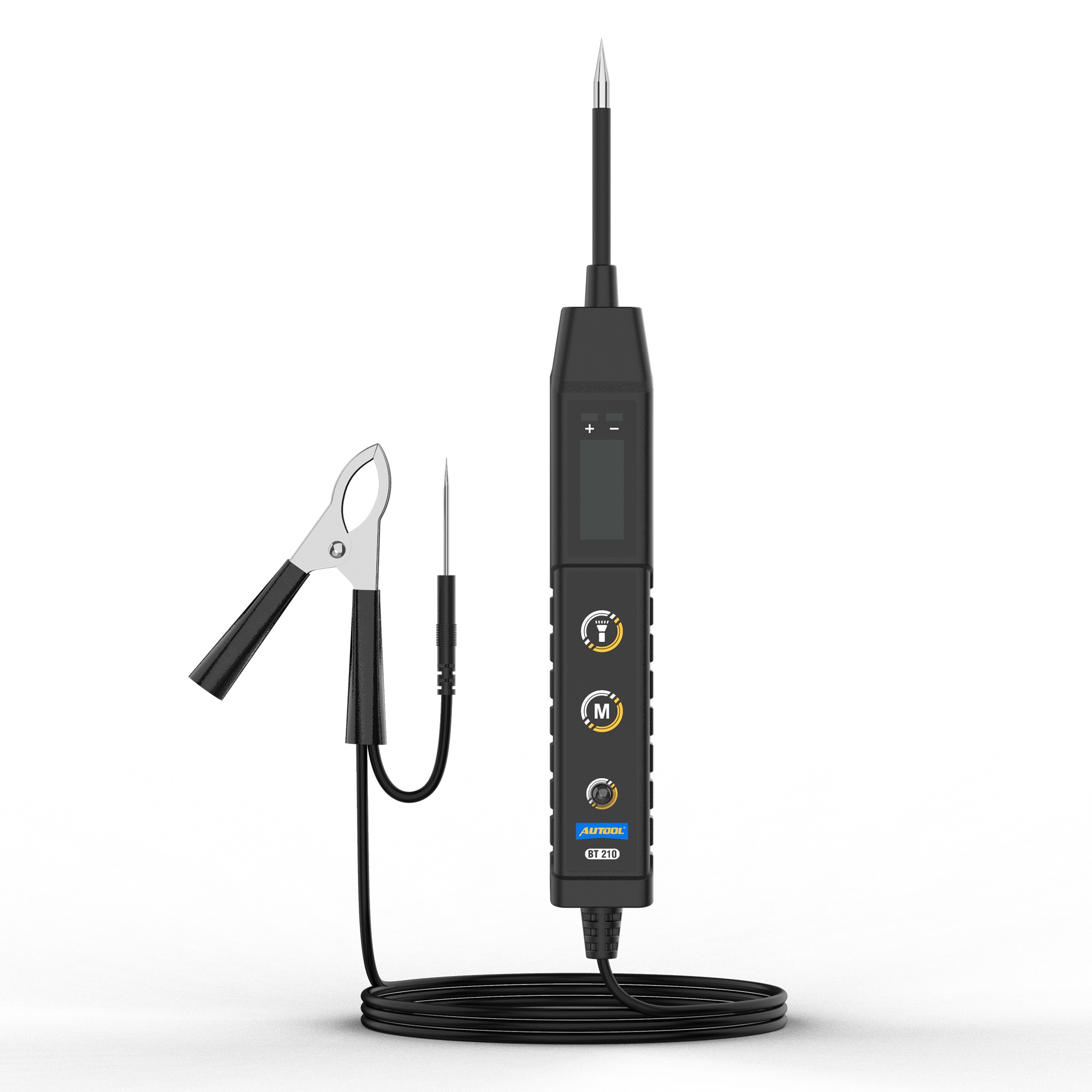
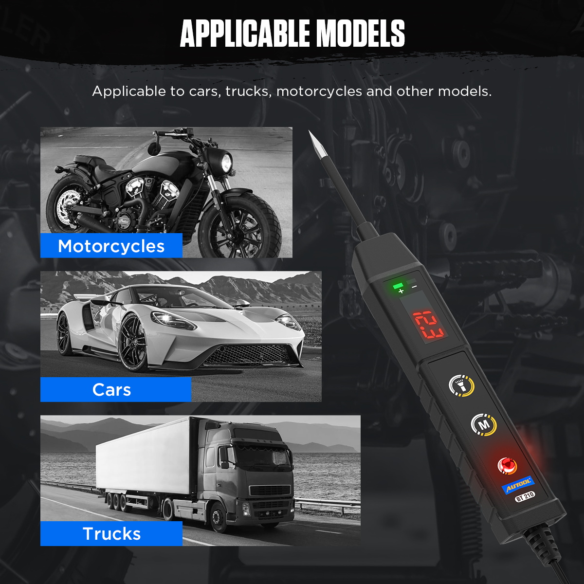
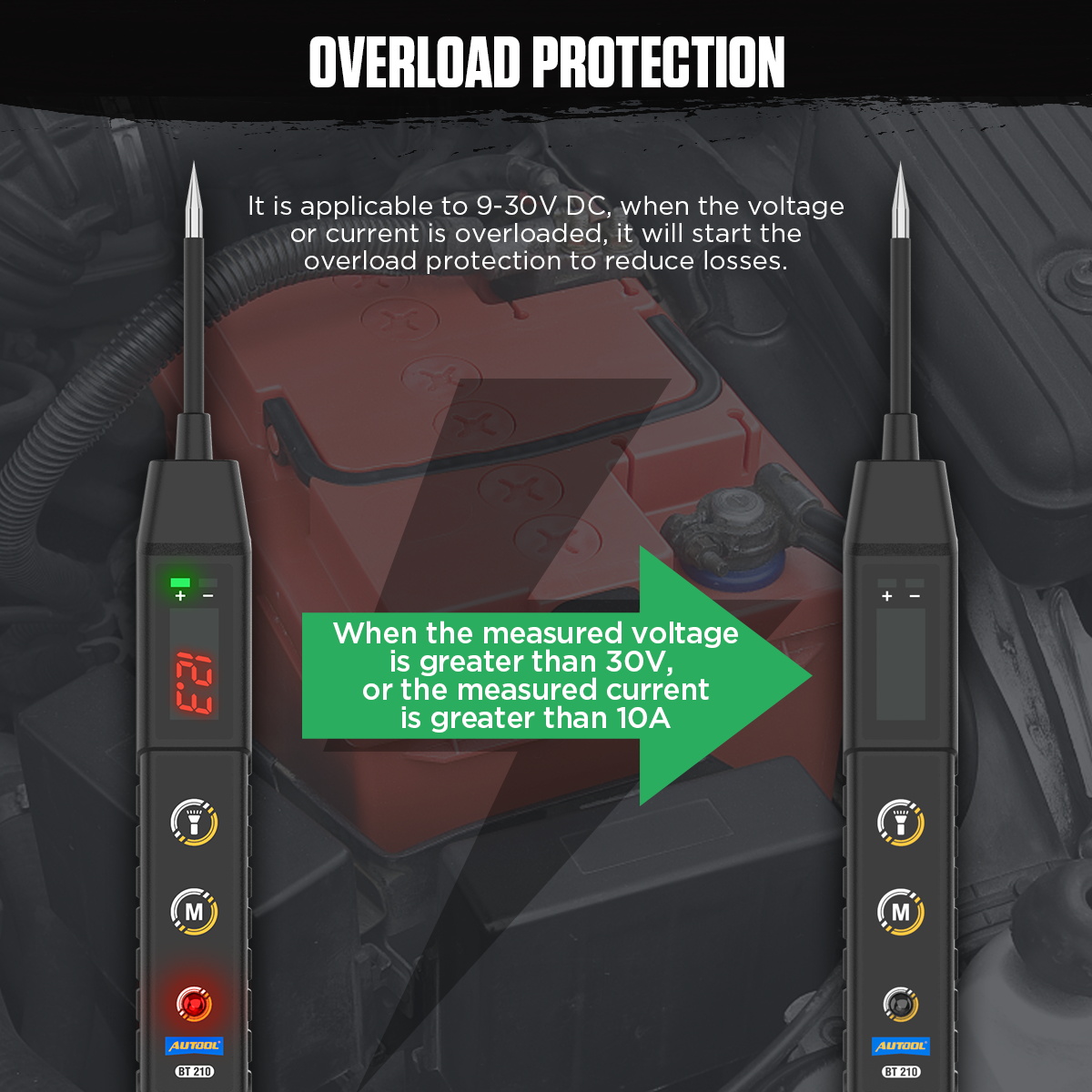
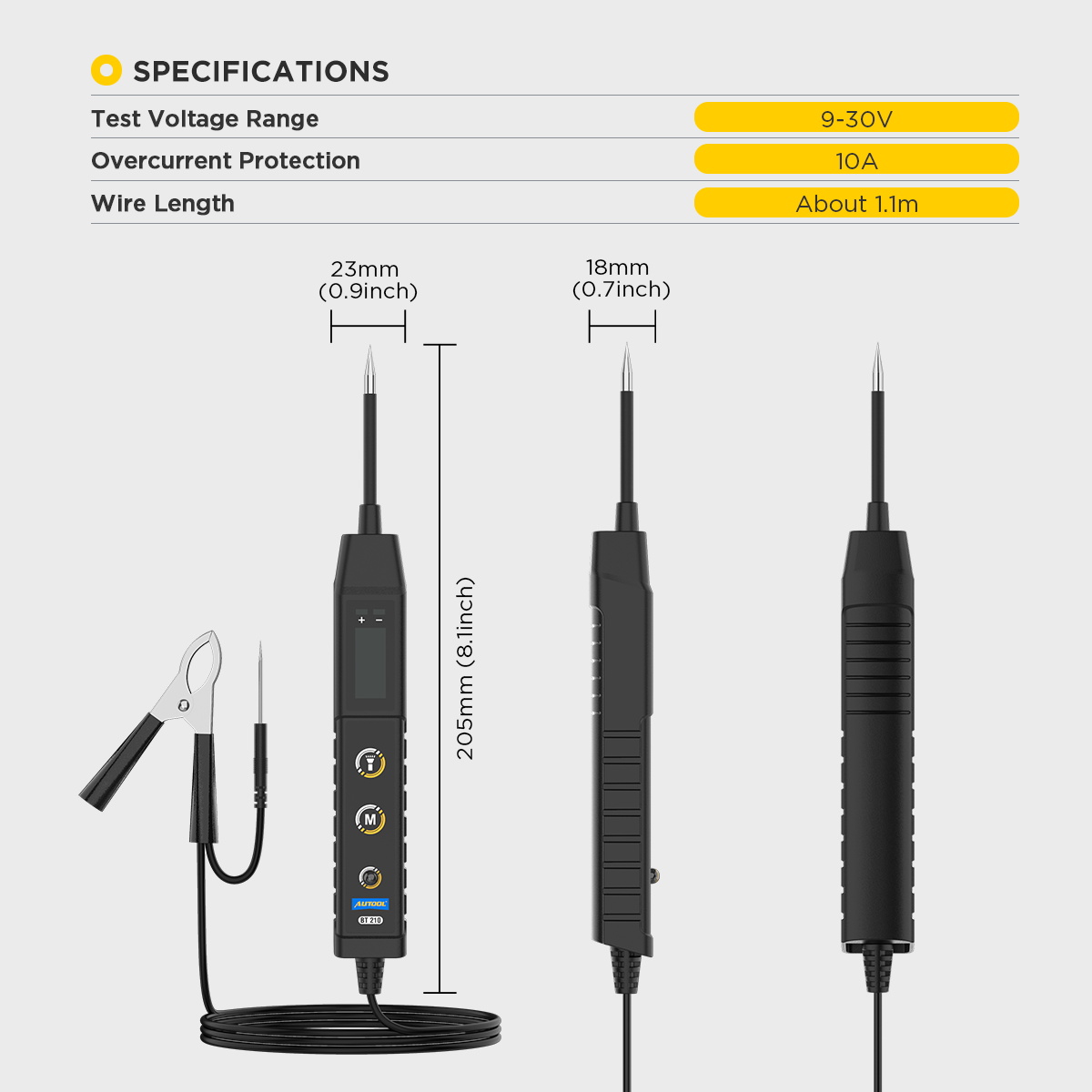
Professional Circuit Tester: Suitable for testing electrical systems with DC voltages ranging from 9V to 30V, including applications in cars, motorcycles, trucks, excavators, ships, and more
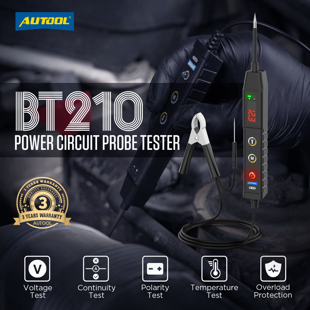
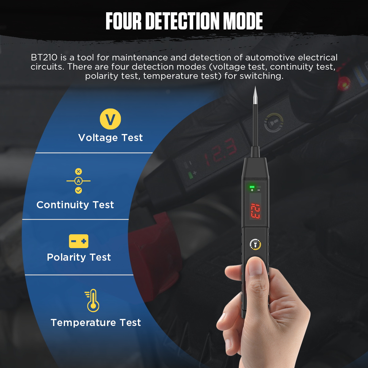
Multiple Testing Modes: Switch freely between four modes: voltage testing, continuity testing, polarity testing, and temperature testing to fully meet all testing needs.
Voltage Testing Function: With a resolution of up to 0.1V and an accuracy of ±0.2V, it precisely detects the voltage value of the tested circuit.
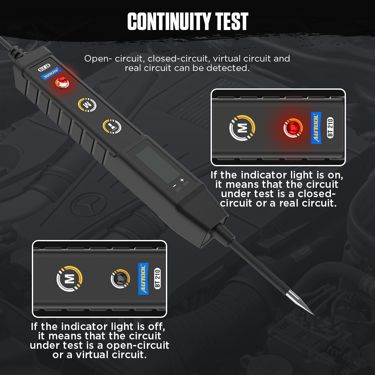
Continuity Testing Function: Supports testing for open circuits, closed circuits, virtual circuits, and real circuits. It can check switches, relays, headlights, taillights, faulty sockets, diodes, fuses, wires, and circuit continuity.
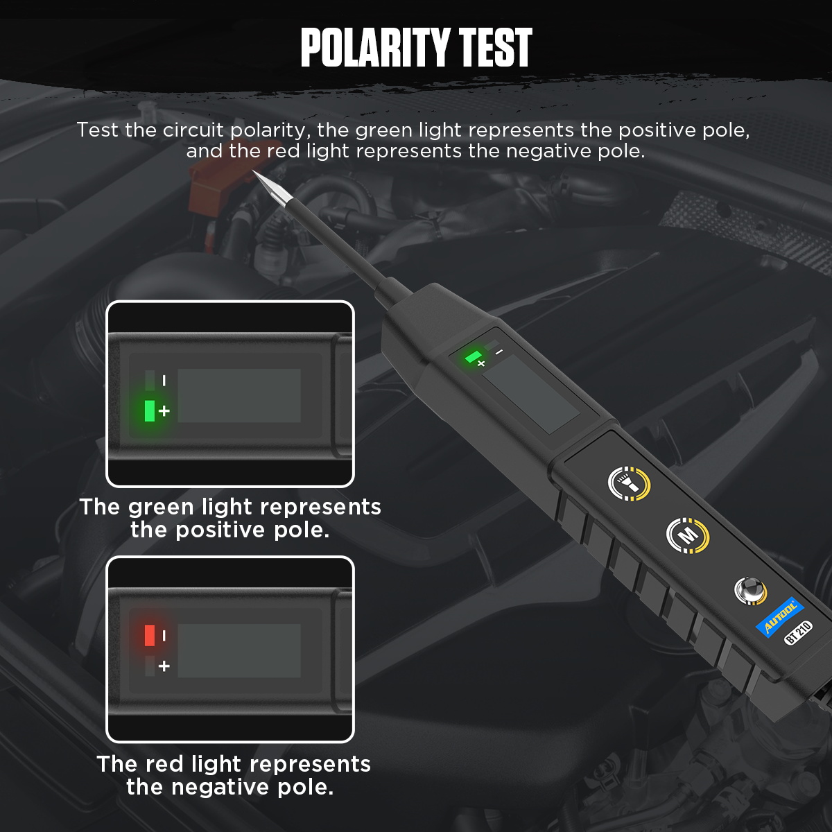
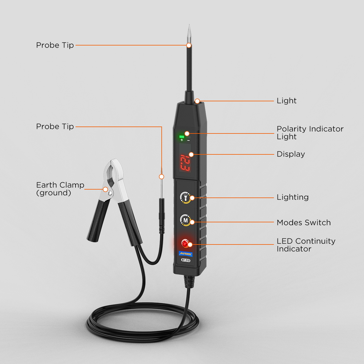
Positive and Negative Polarity Testing Function: When the metal probe contacts the positive terminal, the LED lights up green; when the probe contacts the negative terminal, the LED lights up red
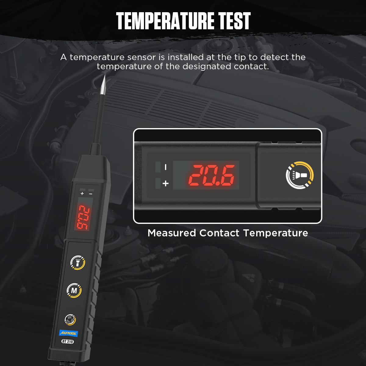
Temperature Testing Function: The probe is equipped with a temperature sensor that can detect the temperature of a specific contact point.
Overload Power-Off Protection: When the measured voltage exceeds 30V or the measured current exceeds 10A, the circuit tester activates the power-off protection function.
High-Quality Tester: Made with high-quality materials, featuring China Compulsory Certification (CCC). It is designed to be leak-proof, ensuring safety and reliability.
Highly Sensitive Probe: The probe is fine, durable, and wear-resistant, allowing easy insertion into hard-to-reach automotive circuits.
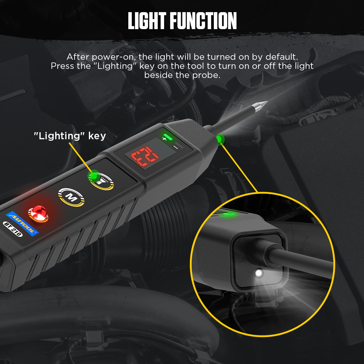
Backlit LED Display: Clear and precise voltage and temperature readings of the measured circuit, visible in both strong light or dim environment.
Operating Instruction
Voltage Test
Connect the clip to the positive terminal of the battery.
1. Press the “M” button on the tester briefly to switch to voltage testing mode.
2. Contact the tip of the test probe with the test point, and the LED display will automatically show the voltage value of the measured circuit.
Continuity Test
1. Connect the clip to the positive terminal of the battery.
2. Press the “M” button on the tester briefly to switch to continuity test mode.
3. Contact the tip of the test probe with the test point. If the LED lights up red, it indicates the circuit is continuous or a real circuit. If the LED does not light up, it indicates the circuit is open or a phantom circuit.
Polarity Test
1. Connect the clip to the positive terminal of the battery.
2. Press the “M” button on the tester briefly to switch to polarity test mode.
3. Contact the tip of the test probe with a test point with an unknown polarity. If the LED on the tester lights up green, it indicates the test point is positive voltage. If the LED lights up red, it indicates the test point is negative voltage.
Temperature Test
1. Connect the clip to the positive terminal of the battery.
2. Press the “M” button on the tester briefly to switch to temperature test mode.
3. Contact the tip of the test probe with the test point, and the LED display will automatically show the temperature value of the measured circuit.